Handheld aluminum foil cover clamping mechanism
A technology of clamping mechanism and aluminum foil cover, which is applied in the direction of flanged bottle caps, etc., can solve the problems of large volume, inconvenient handling and complex structure of the capping machine, and achieve the effect of easy operation and portability, simple structure and light weight
- Summary
- Abstract
- Description
- Claims
- Application Information
AI Technical Summary
Problems solved by technology
Method used
Image
Examples
Embodiment 1
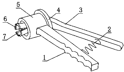
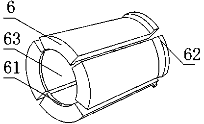
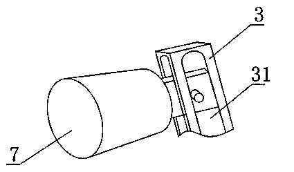
[0025] Such as Figure 1 to Figure 4 , the hand-held aluminum foil cover clamping mechanism provided by the present invention includes a claw tube 5, at least two claws 6, a claw tightening column 7, a fixed handle 1 and a movable handle 3, and the claw tube 5 is provided with Through the circular holes at both ends, the claws 6 are in the shape of arc plates, and the two sides of the claws 6 are closed to form a truncated cone, the smaller end of the truncated cone is located in the circular hole, and the inside of the truncated cone forms a cone. Cavity 63, the inner arc surface of claw 6 is all provided with the inward protrusion 61 that protrudes relative to respective inner arc surface, and described inner protrusion 61 is positioned at the larger end of conical truncated cone, and the smaller end of conical cavity 63 is connected with the cone. The smaller end of the platform is in the same direction, and one end of the jaw tightening column 7 is columnar, and the jaw ti...
Embodiment 2
[0029] This embodiment is further limited on the basis of embodiment 1: as Figure 1 to Figure 4 , also includes a fulcrum 8 fixedly connected to the claw barrel 5, one end of the movable handle 3 is provided with a chute 31 along the length direction of the movable handle 3, one end of the claw tightening column 7 is located in the chute 31 and Can slide along the chute 31, and the movable handle 3 is hingedly connected with the fulcrum 8.
[0030] The above settings make the pulling of the movable handle 3 to the claw tightening column 7 a lever action mode, which is convenient for braking the claw tightening column 7. At the same time, in order to further optimize the force applied to the present invention, the fixed handle 1 and the movable handle 3 on the same plane.
[0031] In order to improve the working efficiency of the present invention, the fixed handle 1 and the movable handle 3 can rebound after the aluminum foil cover is clamped, and a spring 2 is also included...
Embodiment 3
[0033] The present embodiment is further limited on the basis of embodiment 2: as Figure 1 to Figure 4 In order to prevent the claws 6 from slipping out of the claw barrel 5 during the working process of the present invention, the outside of the smaller end of the truncated cone surrounded by the claws 6 is also provided with a convex 62, which is located at the rear of the truncated cone. The end of the jaw barrel 5 is provided with an external thread, and the end cap 4 threadedly connected with it is fixed on the external thread, and an annular outer spit groove 51 is arranged between the end cap 4 and the side wall of the jaw barrel 5 , the outer protrusion 62 is located in the outer protrusion groove 51 .
PUM
 Abstract
Description
Claims
Application Information
 - R&D
- Intellectual Property
- Life Sciences
- Materials
- Tech Scout
- Unparalleled Data Quality
- Higher Quality Content
- 60% Fewer Hallucinations
Browse by: Latest US Patents, China's latest patents, Technical Efficacy Thesaurus, Application Domain, Technology Topic, Popular Technical Reports.
© 2025 PatSnap. All rights reserved.Legal|Privacy policy|Modern Slavery Act Transparency Statement|Sitemap|About US| Contact US: help@patsnap.com


