Prefabricated shear wall dry type vertical connecting node and construction method

A prefabricated shear force, vertical connection technology, applied in the direction of walls, building components, buildings, etc., to achieve the effect of less labor, convenient construction, and short construction period

Active Publication Date: 2014-09-10
SOUTHEAST UNIV
View PDF9 Cites 6 Cited by
  • Summary
  • Abstract
  • Description
  • Claims
  • Application Information

AI Technical Summary

Problems solved by technology

The above connection is also a wet connection, and no dry connection has been put into use yet

Method used


Image

  • Prefabricated shear wall dry type vertical connecting node and construction method
  • Prefabricated shear wall dry type vertical connecting node and construction method
  • Prefabricated shear wall dry type vertical connecting node and construction method

Examples


Embodiment 1

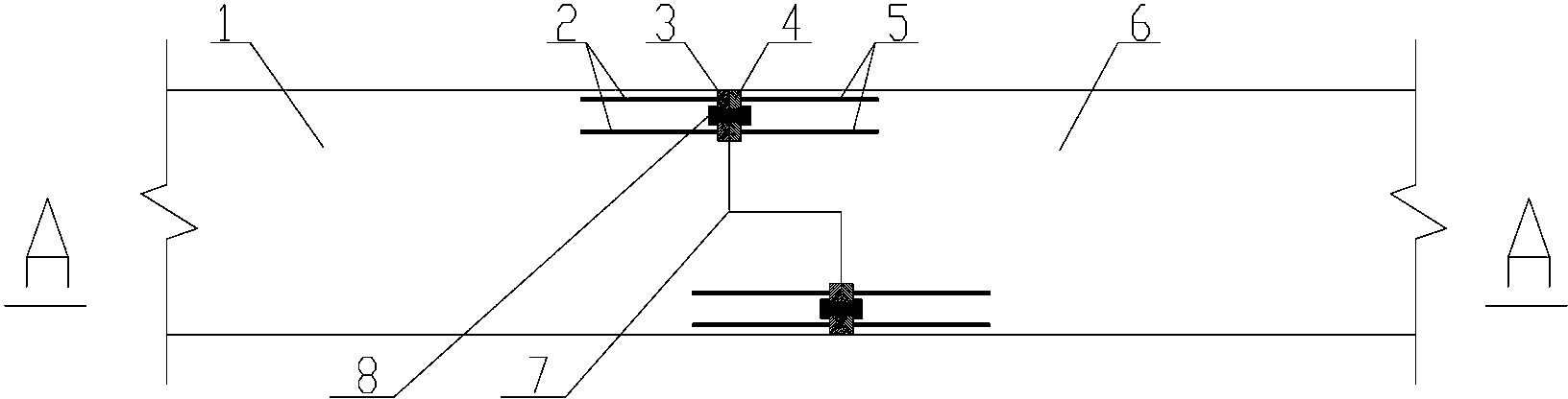
[0027] Embodiment 1: as figure 1 and figure 2 As shown, the prefabricated shear wall dry type vertical connection node of the present embodiment includes the first prefabricated shear wall 1 and the second prefabricated shear wall 6, the first prefabricated shear wall 1 and the second prefabricated shear wall 6 in order to The mouth 7 is connected, and the groove 7 is chiseled. The first prefabricated shear wall 1 at the groove 7 is provided with a first clip-type connector near the inner and outer facades, and the second prefabricated shear wall 1 at the groove 7 The shear wall 6 is provided with a second clip-type connector; the first clip-type connector includes a first anchor plate 3 and a first anchor bar 2 welded to each other, and the first anchor plate 3 is embedded in the connection interface of the tongue and groove, The first anchor bar 2 is anchored in the first prefabricated shear wall 1; the second hairpin connector includes a second anchor plate 4 and a second...

Embodiment 2

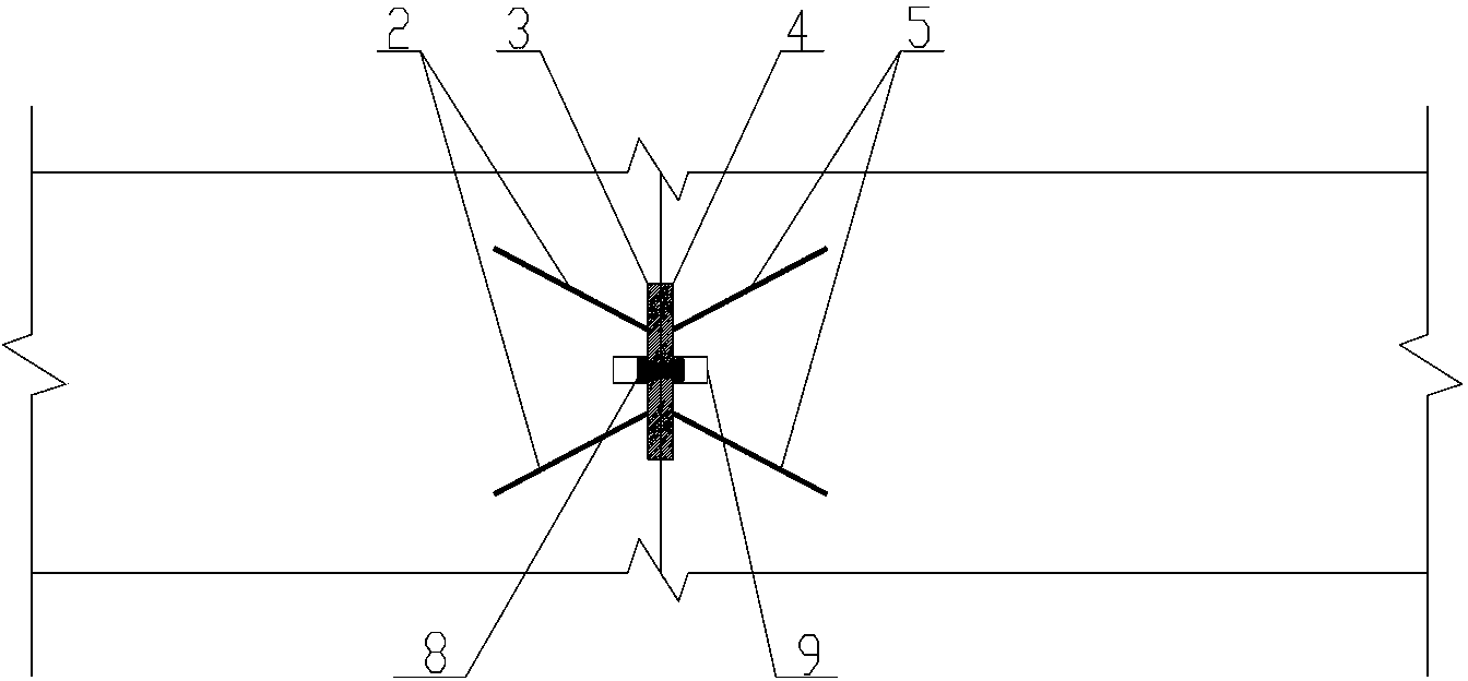
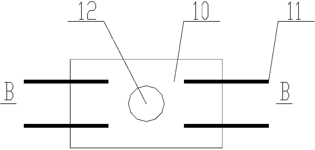
[0035] Embodiment 2: This embodiment is an improvement on the basis of Embodiment 1. The first hairpin connector and the second hairpin connector adopt the same structure, that is, the hairpin connector is defined as a standard part for mass production. Such as image 3 and Figure 4 As shown, the hairpin connector includes a rectangular anchor plate 10 and four anchor bars 11 welded thereon and forming an angle of 45° with the anchor plate 10. The anchor bars 11 have a fixed end welded to the anchor plate 10 and a The free end of the plate 10. It is arranged symmetrically along the bolt hole 12 in the middle of the anchor plate, and its free end is far away from the bolt hole 12.


PUM


Abstract

The invention discloses a prefabricated shear wall dry type vertical connecting node and a construction method. The vertical connecting node comprises mutually connected prefabricated shear walls, wherein a tongue and groove joint is arranged at a connecting interface of the prefabricated shear walls; the tongue and groove joint is subjected to hacking treatment; hairpin type connecting elements are respectively buried in positions, near the inner and the outer facades of the prefabricated shear walls, of the tongue and groove joint; the hairpin type connecting elements comprise mutually welded anchor plates and anchor bars; the outer sides of the anchor plates are exposed out of the end surface of the tongue and groove joint; the anchor bars are anchored in the prefabricated shear walls arranged at the inner sides of the anchor plates; the centers of the anchor plates are provided with screw bolt holes; grooves are formed in the prefabricated shear walls positioned at the inner sides of the screw bolt holes; the hairpin type connecting elements arranged at the two sides of the connecting interface are mutually symmetrical; in addition, screw bolts are arranged in a pair of screw bolt holes; and the two ends of the screw bolts are positioned in the grooves. The construction method comprises the steps of prefabricated shear wall manufacturing, butt joint of the hairpin type connecting elements at the tongue and groove joint part, screw bolt installing, mortar filling and the like. The vertical connecting node basically realizes a fully dry type connecting method, the connecting intensity and the bearing force are high, and the node conforms to the requirements of building industrialization and housing industrialization.

Description

technical field [0001] The invention relates to a prefabricated shear wall dry vertical connection node form and a construction method, belonging to the technical field of building structures. Background technique [0002] The shear wall structure is a structure composed of shear walls that can withstand vertical and horizontal loads. Compared with other structural forms, shear walls have higher seismic performance and better comfort, and are widely used in multi-storey and high-rise buildings. . In recent years, with the acceleration of construction industrialization and housing industrialization, prefabricated shear wall structures have become more and more widely used, which brings about the connection problem of shear walls. Most of the existing connection forms are all-wet connections, and a small part are dry-wet hybrid connections. Chinese patent document CN101503896A discloses a vertical connection node of an inline shear wall, including the first prefabricated shea...

Claims


Application Information

Patent Timeline
Patent Type & Authority Applications(China)
IPC IPC(8): E04B2/00
CPCE04B2/00E04G21/14
Inventor 梁书亭孙崇芳朱筱俊
Owner SOUTHEAST UNIV
Why Eureka
Try Eureka