
Integrally fabricated box-shaped multi-ribbed composite floor

A monolithic and floor-slab technology, which is applied to floors, building components, buildings, etc., can solve the problems of low industrial production level, low prefabrication rate, labor and time-consuming problems of hollow ribbed floors, etc., and achieve the reduction of poor sound insulation performance, hollow The effect of high efficiency and simple construction process

Active Publication Date: 2014-09-10
CHINA MCC17 GRP
View PDF11 Cites 50 Cited by
  • Summary
  • Abstract
  • Description
  • Claims
  • Application Information

AI Technical Summary

Problems solved by technology

During the actual construction, it is still necessary to arrange the bottom formwork on the lower side of the rib beam reinforcement, and then carry out the construction according to the construction method of the cast-in-place floor; a reinforced concrete hollow floor slab and its construction method (patent application numbers 201010558041.4, 201110099901.7, 201110101206. ), etc. In essence, only innovations have been made in the form of the formwork. The production idea of ​​the hollow-core slab is still to arrange the bottom formwork on the lower side of the rib beam, and then arrange the rib beam and the panel. Generally speaking, it belongs to the category of two-way slabs, and the drawbacks of labor and time-consuming construction have not been fundamentally improved. Therefore, the industrial production level of the above-mentioned several hollow ribbed floors is not high, and the prefabrication rate is low, which does not meet the current industrialization of buildings. the trend of

Method used


Image

  • Integrally fabricated box-shaped multi-ribbed composite floor
  • Integrally fabricated box-shaped multi-ribbed composite floor
  • Integrally fabricated box-shaped multi-ribbed composite floor

Examples


Embodiment Construction

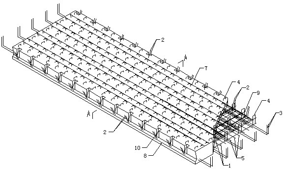
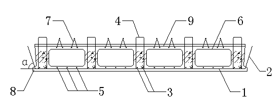
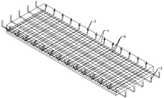
[0042] From Figure 1-5 It can be seen from the figure that: an assembled integral dense-ribbed box-shaped composite floor (referred to as composite floor), is characterized in that: the assembled integral dense-ribbed box-shaped composite floor is mainly composed of the bottom horizontal reinforcement 1, the bottom connection reinforcement 2, The rib beam lower longitudinal reinforcement 3, the rib beam stirrup 4, the bottom longitudinal reinforcement 5, the formwork 6, the truss reinforcement 7, the flange 8, the top horizontal reinforcement 9, the wedge-shaped groove 10 and the concrete layer (that is, the concrete slab), The bottom connecting reinforcing bars 2 are evenly laid at intervals from left to right according to the design, and the connecting reinforcing bars 2 at the bottom are double reinforcing bars in front and rear directions, and the front end and rear end sections of each connecting reinforcing bar 2 are symmetrically respectively The angle α is bent in the...


PUM


Abstract

The invention relates to an integrally fabricated box-shaped multi-ribbed composite floor, and belongs to a prefabricated concrete structural component. The integrally fabricated box-shaped multi-ribbed composite floor is characterized in that the composite floor mainly comprises bottom transverse reinforcement bars, bottom linkage reinforcement bars, lower ribbed beam longitudinal ribs, ribbed beam stirrups, bottom longitudinal reinforcement bars, shutterings, truss ribs, flanges, top transverse reinforcement bars, wedge-shaped grooves and a concrete layer, wherein the bottom linkage reinforcement bars, the bottom transverse reinforcement bars, the lower ribbed beam longitudinal ribs, the bottom longitudinal reinforcement bars, the ribbed beam stirrups, the top transverse reinforcement bars and the truss ribs form a steel reinforcement framework of the composite floor; the concrete layer is poured with a conventional concrete pouring method, the flanges are arranged at the bottoms of the front side and the rear side of a concrete slab body, the connecting position of two composite floors forms a U-shaped groove by the flanges, and crack pouring of post-poured concrete is facilitated; and the wedge-shaped grooves are formed in the front side part and the rear side part of the concrete slab body at intervals respectively, the wedge-shaped grooves between every two adjacent composite floors form shear keys, and the shearing resistance between the composite floors is increased.

Description

technical field [0001] The invention belongs to prefabricated assembled concrete structural parts, in particular to an assembled integral composite floor slab. Background technique [0002] Construction industrialization is the development direction of my country's construction industry (Ministry of Construction [1995] No. 188 "Outline of Development of Construction Industrialization"). At present, the ideal systems that can promote the sound and rapid development of construction industrialization include precast concrete PC (Precast Concrete) system and SI system (SI system, that is, the construction system in which the structural part Skeleton and the supporting decoration part Infill are separated). [0003] The PC (Precast Concrete) system, that is, the precast concrete structure system, as a structural form in line with industrial production methods, has the advantages of fast construction speed, low labor intensity, less noise pollution, less wet work, and easy control...

Claims


Application Information

Patent Timeline
IPC IPC(8): E04B5/19
Inventor 潘金龙马军卫尹万云
Owner CHINA MCC17 GRP
Learn More