Gas-liquid separation evaporator

A gas-liquid separation and evaporator technology, applied in evaporator/condenser, refrigeration and liquefaction, refrigeration components, etc., can solve the problems of low refrigeration efficiency, large vapor-liquid two-phase resistance, etc. Large heat transfer coefficient, the effect of improving heat transfer efficiency

Active Publication Date: 2016-08-24
佛山市顺德区君胜电器实业有限公司
View PDF7 Cites 0 Cited by
  • Summary
  • Abstract
  • Description
  • Claims
  • Application Information

AI Technical Summary

Problems solved by technology

[0003] Its main disadvantage is that the transmission pipe is a continuous extension pipe, and the refrigerant liquid in the rear can only continue to evaporate after the steam in the front is discharged, so that there is a large vapor-liquid two-phase resistance in the pipe, resulting in low refrigeration efficiency

Method used


Image

  • Gas-liquid separation evaporator
  • Gas-liquid separation evaporator

Examples


Embodiment 1

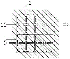
[0013] in figure 1 In the first embodiment shown, the gas-liquid separation evaporator includes a transmission tube 1 and a heat sink 2; wherein the transmission tube 1 forms a multi-connected network structure composed of a large number of squares, and the nodes between the transmission tubes are The multi-way connector 11 is connected, which not only facilitates assembly, but also ensures the airtightness of the mesh structure.

[0014] The refrigerant enters the evaporator from the left side, and is divided into two parts, vapor and liquid due to gravity. The gas quickly passes through the upper part of the multi-connected network structure, and the liquid flows into the lower part of the multi-connected network structure without air pressure. Evaporation is realized under constrained conditions; in this structure, gas and liquid are completely separated, and the resistance of the two-phase flow of vapor and liquid is greatly reduced, which effectively improves the evaporative ...

Embodiment 2

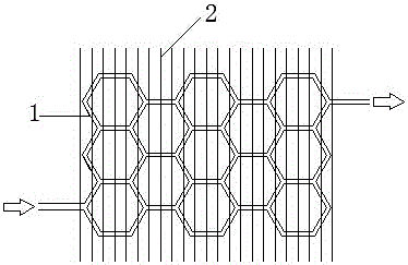
[0018] in figure 2 In the second embodiment shown, the difference from the first embodiment is that the multi-connection network structure of the gas-liquid separation evaporator is honeycomb, and the connection nodes between the transmission pipes 1 are also connected by multi-connections. The head 11 is connected; compared to the first embodiment, the specific structure of the transfer tube is changed, and the gas-liquid separation can also be realized. The inner and outer surfaces of the transfer tube can be corrugated, which can also increase the heat transfer area and achieve the same effect.

[0019] In addition, the multi-connected network structure formed by the transfer pipe 1 in the evaporator may also be a three-dimensional grid or the like.


PUM


Abstract

The invention provides a gas-liquid separation evaporator; the evaporator comprises a transmission tube and a heat sink, the transmission tube is a multi-connected mesh structure, the heat sink is distributed in parallel, and is clamped on the transmission tube Corrugated pipes are used for the transmission pipes, and the nodes between the transmission pipes are connected by multi-pass connectors. The multi-pass network structure can realize gas-liquid separation, effectively increase the heat exchange area, and speed up heat dissipation. The evaporator can effectively Reduce vapor-liquid two-phase flow resistance and improve refrigeration efficiency.

Description

technical field [0001] The invention relates to the field of air conditioner accessories, in particular to an air conditioner evaporator. Background technique [0002] At present, the evaporator transfer tubes of commonly used air conditioners are mostly serpentine tubes, and the transfer tubes are covered with fins. The refrigerant is transmitted from the transmission tube, after absorbing heat, it is converted from a liquid state to a gaseous state, and then transmitted to the compressor. The fins closely connected with the transmission tube transfer heat, increase the heating area, and rely on air convection to dissipate heat. [0003] Its main disadvantage is that the transmission pipe is a continuous extension pipe, and the refrigerant liquid in the rear can only continue to evaporate after the steam in the front is discharged, which makes the pipe have a large vapor-liquid two-phase resistance, resulting in low refrigeration efficiency. Contents of the invention [...

Claims


Application Information

Patent Timeline
Patent Type & Authority Patents(China)
IPC IPC(8): F25B39/02
Inventor 梁永锋
Owner 佛山市顺德区君胜电器实业有限公司
Why Eureka
Try Eureka