
A frequency jitter circuit and switching power supply

A technology of frequency jitter and power supply, applied in the direction of electrical components, output power conversion devices, etc., can solve the problems of many components, difficult implementation, and complex implementation

Active Publication Date: 2017-11-21
HISENSE BROADBAND MULTIMEDIA TECH
View PDF5 Cites 0 Cited by
  • Summary
  • Abstract
  • Description
  • Claims
  • Application Information

AI Technical Summary

Problems solved by technology

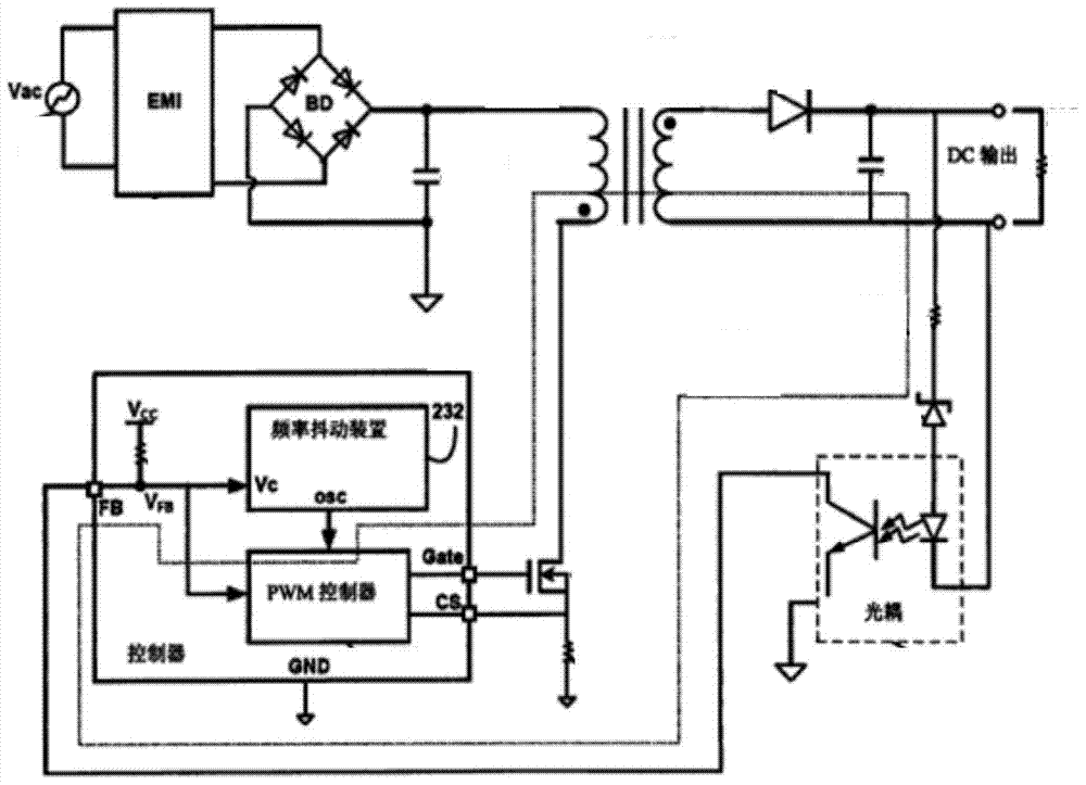
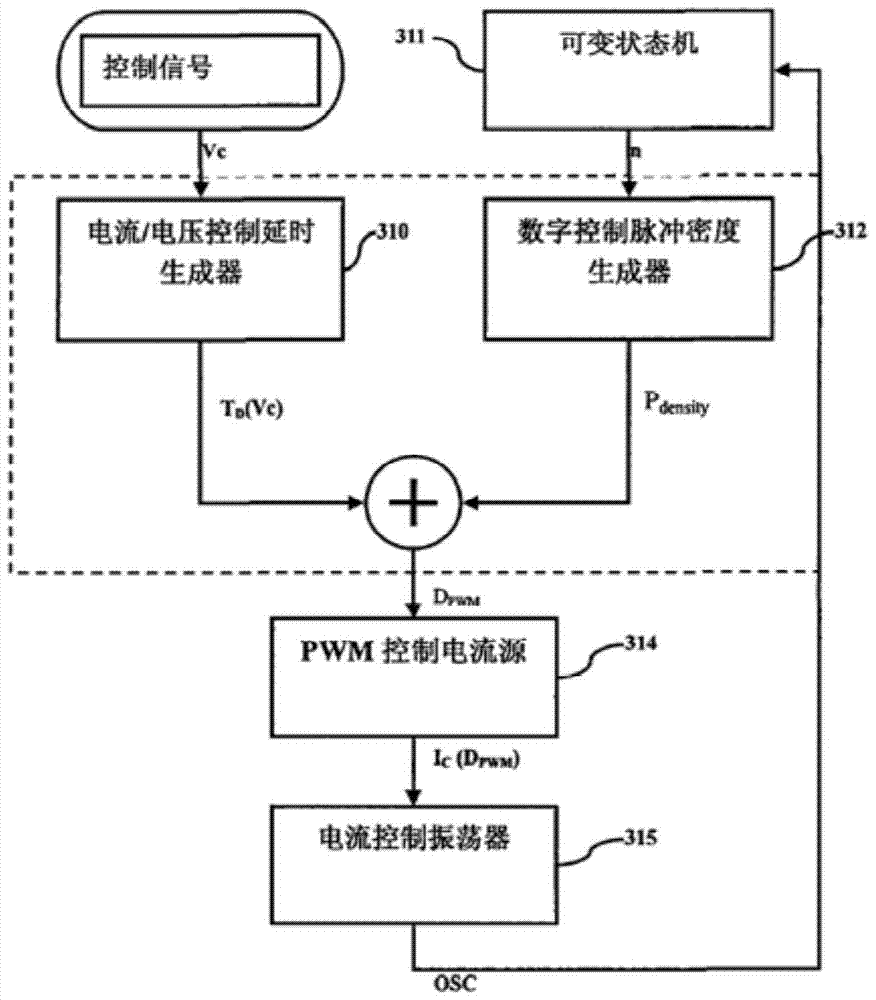
[0004] Although figure 1 and figure 2 The frequency dithering method shown can realize the frequency dithering of the switching power supply, thereby suppressing EMI interference, but the circuit uses many devices, the implementation is relatively complicated, and it is not conducive to integration; especially for PWM controllers that do not have frequency dithering technology , built on the periphery of the PWM controller such as figure 2 The frequency dithering setup shown is not easy and will be more expensive

Method used


Image

  • A frequency jitter circuit and switching power supply
  • A frequency jitter circuit and switching power supply
  • A frequency jitter circuit and switching power supply

Examples


Embodiment Construction

[0034] The following will clearly and completely describe the technical solutions in the embodiments of the present invention with reference to the accompanying drawings in the embodiments of the present invention. Obviously, the described embodiments are only some, not all, embodiments of the present invention. Based on the embodiments of the present invention, all other embodiments obtained by persons of ordinary skill in the art without creative efforts fall within the protection scope of the present invention.

[0035]First introduce the technical element relevant to the embodiment of the present invention:

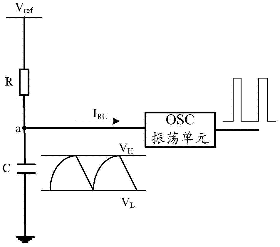
[0036] like image 3 Shown is the existing RC charge and discharge circuit, through the charge and discharge of the capacitor C to generate a periodic signal with a fixed frequency, the oscillator unit (Open Source Commerce, referred to as OSC) processes this periodic signal, and outputs a clock signal with a fixed frequency, if the When the oscillating unit is built...


PUM


Abstract

The invention discloses a frequency shaking circuit and a switching power supply, relates to the technical field of switching power supplies, realizes frequency shaking simply and at low cost, and is easy to integrate. The frequency jitter circuit includes a first resistance unit, a second resistance unit, a first capacitance unit, a first power supply, a second power supply and an oscillator; the first power supply passes through the first resistance unit and the first capacitance unit Connected to the first end of the first power supply, the first power supply is used to generate a constant voltage signal; the second power supply is connected to the second end of the first capacitor unit, and the second power supply is used to generate a periodically varying voltage signal ; The oscillator is connected to the first end of the first capacitance unit; the first end of the second resistance unit is connected to the second end of the first capacitance unit, and the second end is connected to the ground.

Description

technical field [0001] The invention relates to the technical field of switching power supplies, in particular to a frequency dithering circuit and a switching power supply. Background technique [0002] With the rapid development of electronic power technology, the relationship between power electronic equipment and people's work and life is becoming increasingly close. Switching power supply is widely used in various power electronic equipment because of its miniaturization and portability. Among them, the switching power supply can work at a higher frequency, but the switching power supply working at a higher frequency will cause a strong electromagnetic interference (ElectroMagnetic Interference, EMI for short) signal, which will interfere with the device through conduction and radiation. Normal work, pollute the electromagnetic environment. [0003] At present, one of the effective ways to suppress EMI is to introduce frequency jitter technology, so that the switching ...

Claims


Application Information

Patent Timeline
Patent Type & Authority Patents(China)
IPC IPC(8): H02M1/44
Inventor 李秀宇余超群王文明秦德胜
Owner HISENSE BROADBAND MULTIMEDIA TECH
Learn More