Solar cell fabrication method and solar cell

A technology of solar cells and manufacturing methods, which is applied to circuits, electrical components, photovoltaic power generation, etc., can solve the problems of solar cell performance degradation and increase, and achieve the effect of reducing the amount of silver used

Inactive Publication Date: 2014-09-10
SHARP KK
View PDF12 Cites 6 Cited by
  • Summary
  • Abstract
  • Description
  • Claims
  • Application Information

AI Technical Summary

Problems solved by technology

[0011] However, in the case of reducing the amount of silver used in the electrode part 102, due to the increase in

Method used


Image

  • Solar cell fabrication method and solar cell
  • Solar cell fabrication method and solar cell
  • Solar cell fabrication method and solar cell

Examples


Embodiment

[0050] Next, embodiments of the present invention will be described in detail.

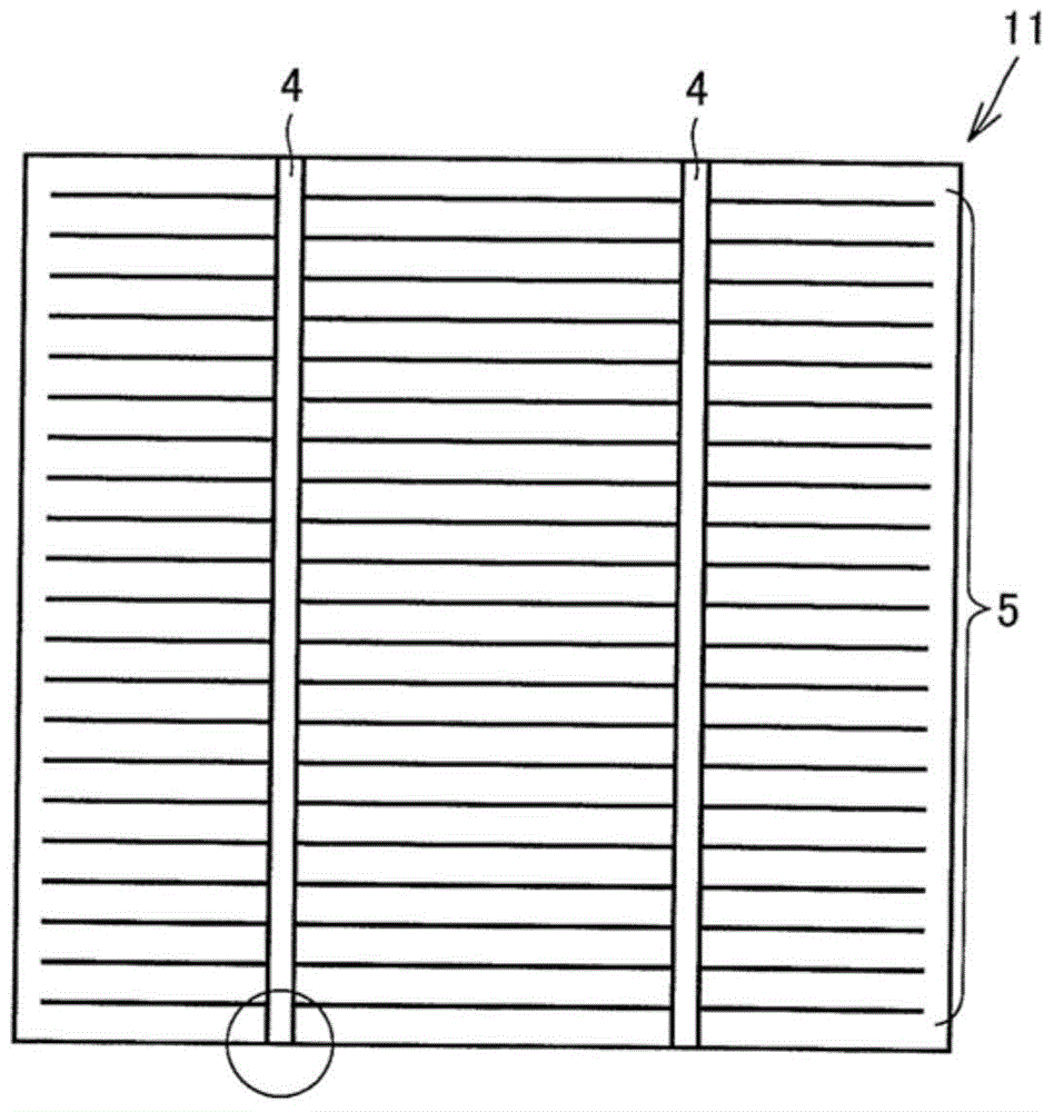
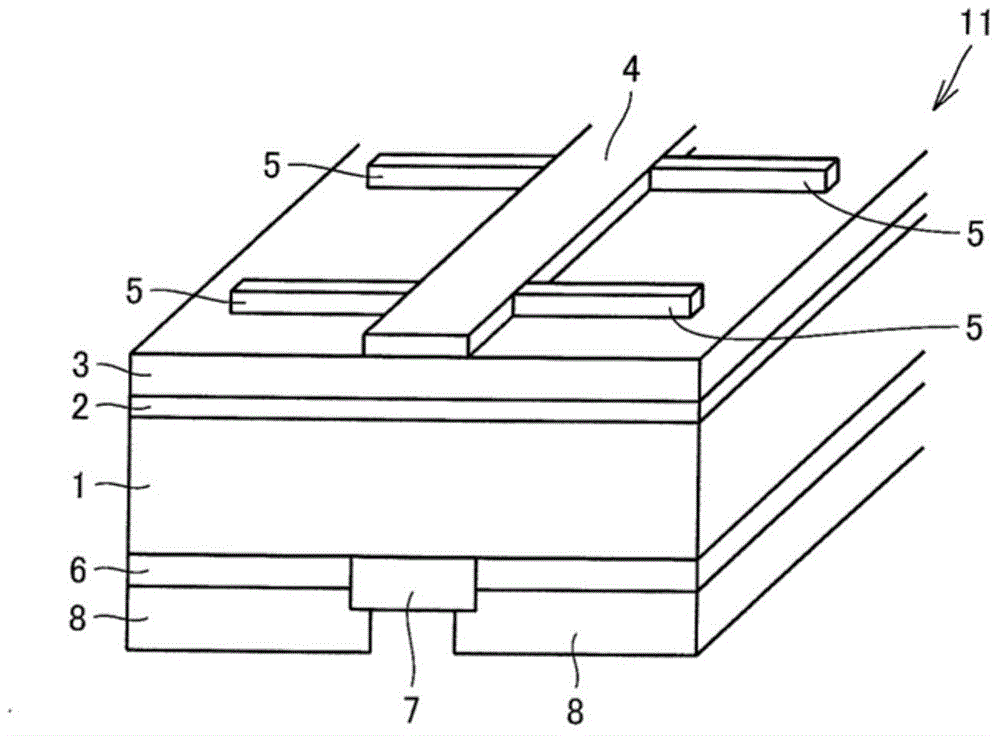
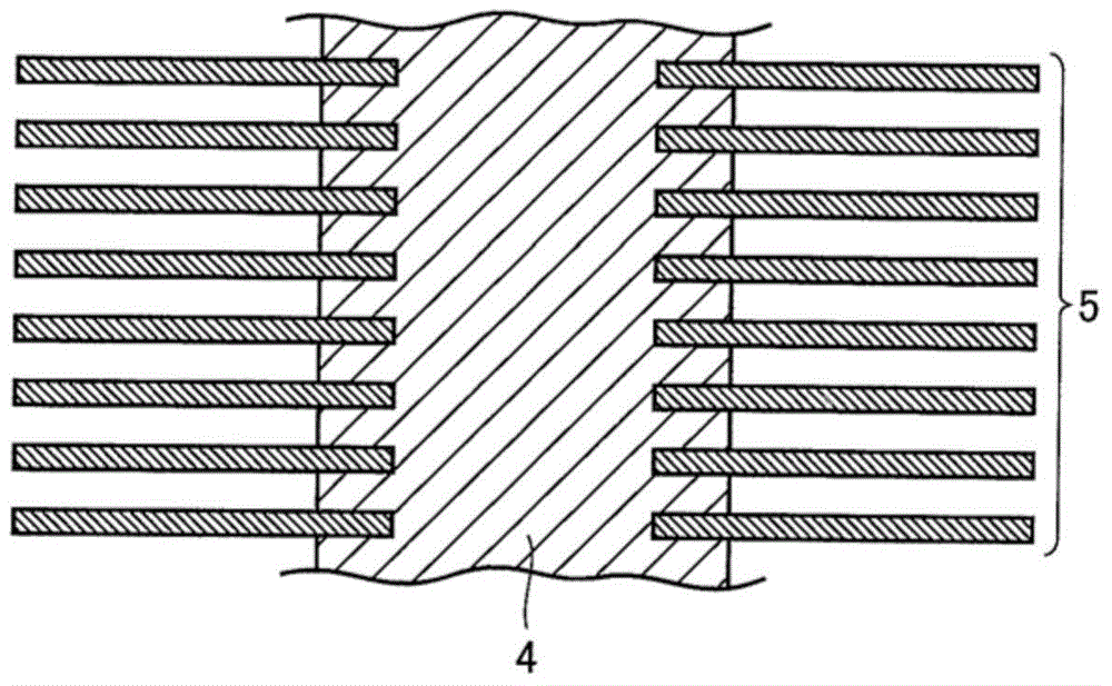
[0051] In the following examples, the same silver paste was used to form the sub-gate electrode 5 , and the silver paste used to form the main gate electrode 4 was variously changed, and its characteristics were investigated. The silver paste used to form the sub-gate electrode 5 was used as a reference silver paste. In addition, all the silver pastes used in the following examples have burn-through properties.

[0052]

[0053] In the first to fourth examples, the solar cells of the first to fourth examples were produced using silver pastes having different silver content and glass frit content in the silver paste used for forming the busbar electrode 4 . Also, in the first to fourth embodiments, as described above, the sub-gate electrode 5 is formed using the reference silver paste. In addition, as a reference, a reference solar cell in which both the main grid electrode 4 and the sub-gate e...


PUM

PropertyMeasurementUnit
Softening pointaaaaaaaaaa
The average thicknessaaaaaaaaaa

Abstract

Provided are a solar cell fabrication method and a solar cell in which the degree of inclusion of silver in a silver paste which is used in forming a substrate surface main grid electrode is made lower than the degree of inclusion of silver in the silver paste which is used in the formation of a sub-grid electrode.

Description

technical field [0001] The present invention relates to a method for manufacturing a solar cell and the solar cell. Background technique [0002] In recent years, expectations for a solar cell that directly converts solar energy into electrical energy as a next-generation energy source have been rapidly increasing, especially from the viewpoint of global environmental protection. There are various types of solar cells such as solar cells using compound semiconductors and organic materials, but solar cells using silicon crystals are currently the mainstream. [0003] Currently, the structure of the most manufactured and sold solar cells is a structure in which electrodes are formed on the light-receiving surface and the back surface opposite to the light-receiving surface. [0004] Figure 6 A schematic plan view showing a light-receiving surface of a conventional solar cell disclosed in Japanese Patent Application Laid-Open No. 2004-14566 (Patent Document 1), Figure 7 mea...

Claims


Application Information

Patent Timeline
IPC IPC(8): H01L31/18H01L31/04H01L31/0224
CPCH01L31/0224H01L31/18H01L31/022425Y02E10/50H01L31/04H01L31/0512H01L31/022433H01L31/02168
Inventor 田中聪大石嘉弘
Owner SHARP KK
Why Eureka
Try Eureka