Supercharge Your Innovation With Domain-Expert AI Agents!

Fiber optic magnetic flux sensor for application in high voltage generator stator bars

A magnetic flux sensor and sensor technology, applied in the direction of measuring magnetic variables, instruments, electromechanical devices, etc., can solve problems affecting reflection properties, etc.

Inactive Publication Date: 2014-09-10
SIEMENS ENERGY INC
View PDF6 Cites 9 Cited by
  • Summary
  • Abstract
  • Description
  • Claims
  • Application Information

AI Technical Summary

Problems solved by technology

This strain slightly changes the pitch of the reflective grating lines in the FBG, thereby affecting its reflective properties

Method used


Image

  • Fiber optic magnetic flux sensor for application in high voltage generator stator bars
  • Fiber optic magnetic flux sensor for application in high voltage generator stator bars
  • Fiber optic magnetic flux sensor for application in high voltage generator stator bars

Examples


Embodiment Construction

[0016] The following discussion of embodiments of the invention relating to MBG sensors for measuring the force acting on a stator bar of a high voltage generator is merely exemplary in nature and is not intended to limit the invention or its application or use in any way. The radial component of the magnetic flux on .

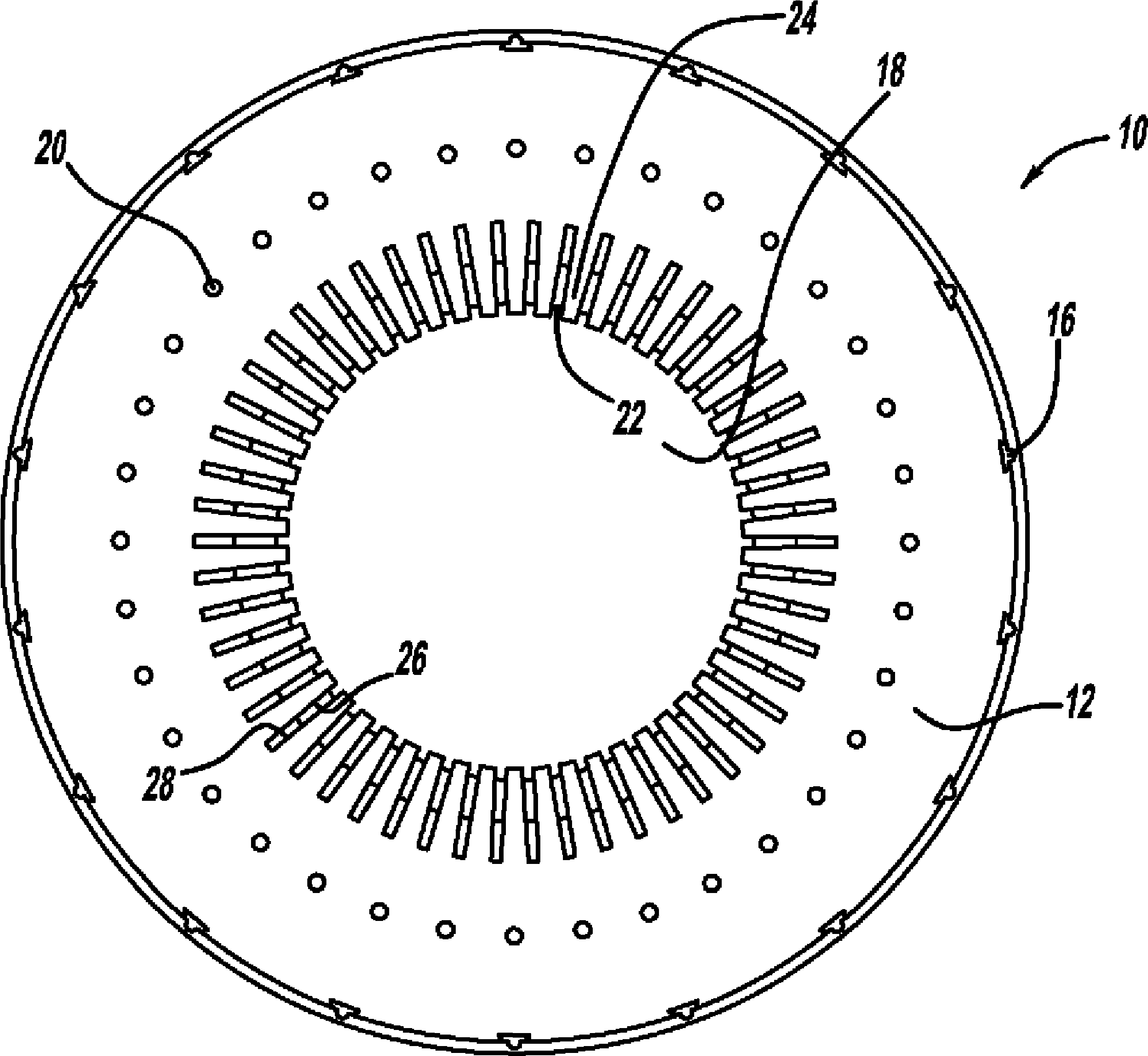
[0017] figure 1 is a cutaway perspective view of a stator core 10 of a high voltage generator and figure 2 is a sectional view of the stator core 10 . The stator core 10 includes a magnetic cylindrical portion 12 formed from an assembly of stacked thin iron lamination segments aligned by key bars 16 and defining an inner bore 18 . A series of through bolts 20 extend through the lamination segments to compress and hold the segments to form the cylindrical portion 12 . The lamination segments of the cylindrical portion 12 define a series of circumferentially positioned slots 22 that open to the bore 18 and define stator core teeth 24 therebetween. Electrica...


PUM


Abstract

A magnetic flux sensor for measuring the radial component of the magnetic flux impinging on a stator bar of a high voltage generator. The magnetic flux sensor includes a fiber Bragg grating formed in an optical fiber and enclosed within a magnetostrictive coating. The magnetostrictive coating responds to changes in magnetic flux by applying a strain on the fiber that changes the reflected wavelength of the Bragg grating that can be measured to provide a measurement of the flux. In one embodiment, one or more of the magnetic flux sensors is positioned directly within an insulating layer of the particular stator bar.

Description

technical field [0001] The present invention relates generally to fiber optic flux sensors for measuring magnetic flux in stator bars of high voltage generators, and more particularly to a fiber optic flux sensor employing a magnetostrictive Bragg grating (MBG) disposed within an optical fiber in order to measure the action Radial component of the magnetic flux on the stator bars of a high voltage generator. Background technique [0002] High voltage generators for power generation as sources of power are well known in the art. Power plants may include gas turbine engines, each of which rotates a shaft by burning fuel and air in a combustion chamber, which expands over blades, which in turn cause the shaft to rotate. The output shaft of such an engine is coupled to the input shaft of a high voltage generator, which is mounted to a rotor with a special coil construction. Current supplied in the rotor coils creates a magnetic flux around the rotor, and as the rotor rotates, ...

Claims


Application Information

Patent Timeline
Patent Type & Authority Applications(China)
IPC IPC(8): H02K11/00
CPCG01R33/0327H02K11/001H02K3/12H02K11/20
Inventor M.特沃多赫利布E.阿布罗米蒂斯
Owner SIEMENS ENERGY INC
Features
  • R&D
  • Intellectual Property
  • Life Sciences
  • Materials
  • Tech Scout
  • Unparalleled Data Quality
  • Higher Quality Content
  • 60% Fewer Hallucinations
Learn More