Supercharge Your Innovation With Domain-Expert AI Agents!

Image processing apparatus, imaging device, image processing method, and computer-readable recording medium

An image processing device and image technology, applied in image data processing, computing, image enhancement, etc., can solve problems such as large processing costs

Active Publication Date: 2014-09-10
RICOH KK
View PDF11 Cites 10 Cited by
  • Summary
  • Abstract
  • Description
  • Claims
  • Application Information

AI Technical Summary

Problems solved by technology

However, in this method, a large processing cost is required for image segmentation or statistical calculation

Method used


Image

  • Image processing apparatus, imaging device, image processing method, and computer-readable recording medium
  • Image processing apparatus, imaging device, image processing method, and computer-readable recording medium
  • Image processing apparatus, imaging device, image processing method, and computer-readable recording medium

Examples


no. 1 example

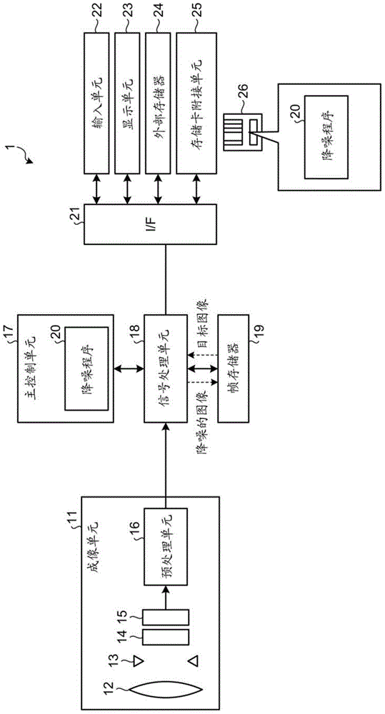
[0031] figure 1 is a block diagram illustrating the overall configuration of the imaging device 1 according to the first embodiment. Specific examples of the imaging device 1 include digital cameras. The imaging device 1 includes an imaging unit 11 that captures an image, a signal processing unit 18 that processes an image signal obtained from the imaging unit 11, a main control unit 17 that controls the entire imaging device 1, a frame memory 19 for storing image data, and a An I / F (Interface) 21 that enables connection with various devices. The I / F 21 is connected to an input unit 22 that receives input from a user, a display unit 23 that displays images and the like, an external memory 24 for storing image data or reading out image data, and a memory card attachment for attaching a storage medium 26 Connect unit 25.

[0032]The imaging unit 11 includes a lens 12 , a diaphragm 13 , an electronic shutter 14 , a photoelectric conversion element 15 , and a preprocessing unit...

no. 2 example

[0089] An image forming apparatus according to a second embodiment will be described below. In the imaging device according to the first embodiment, the weight coefficient is calculated based on the mean value and noise variance value of similar pixel groups of the target image. In contrast, the imaging device according to the second embodiment calculates the weight coefficient based on the variance value (pixel variance value) and the noise variance value of the pixel values ​​of similar pixel groups of the target image.

[0090] Hereinafter, differences from the imaging device 1 according to the first embodiment will be described. Figure 10 is a block diagram illustrating the functional configuration of the image processing unit 120 according to the second embodiment. In addition to the functional configuration of the image processing unit 100 of the first embodiment, the image processing unit 120 includes a mean square value calculation unit 121 and a pixel variance value...

no. 3 example

[0108] Similar to the imaging device according to the second embodiment, the imaging device according to the third embodiment calculates weight coefficients based on pixel variance values ​​and noise variance values ​​of similar pixel groups with respect to a target pixel. However, while the imaging device according to the second embodiment calculates the pixel variance value of the pixels of the downsampled image, the imaging device according to the third embodiment does not calculate the pixel variance value of the pixels of the downsampled image. The imaging apparatus according to the third embodiment calculates only the mean square value of the pixels of the downsampled image, and after completing the upsampling, calculates the pixel variance value of the target pixel based on the mean square value.

[0109] The functional configuration of the image processing unit of the imaging device according to the third embodiment is the same as that referred to above Figure 10 The ...


PUM


Abstract

An image processing apparatus includes a decimating unit configured to decimate pixels in a target image to obtain a decimated image containing a smaller number of pixels than the target image; an extracting unit configured to extract similar pixels at each of which a similarity to a pixel of interest is a threshold or more, from a region containing the pixel of interest among pixels of the decimated image; a first calculating unit configured to calculate a correction candidate value based on pixel values of the similar pixels; a second calculating unit configured to calculate a correction candidate value for each decimated pixel, based on the correction candidate value calculated for each pixel of the decimated image; and a correcting unit configured to correct a target pixel value of a target pixel in the target image, based on the correction candidate value calculated by the first or second calculating unit.

Description

technical field [0001] The present invention relates to an image processing device, an imaging device, an image processing method, and a computer-readable recording medium. Background technique [0002] An image captured by an imaging device such as a digital camera or a scanner contains noise such as shot noise or dark current noise due to characteristics of imaging elements and circuits. In order to obtain high-quality images from captured images, it is necessary to reduce the noise in the images. However, if a low-pass filter is simply used to reduce noise, elements that are important in human perception of an image, such as edges, are lost while reducing noise, resulting in low image quality. Therefore, it is necessary to adaptively reduce noise according to the characteristics of image regions. [0003] As noise reduction techniques, ε-filters and bilateral filters have been developed (see Non-Patent Document 1 (Hiroshi Harashima, Kaoru Odajima, Yoshiaki Shishikui, Hi...

Claims


Application Information

Patent Timeline
Patent Type & Authority Applications(China)
IPC IPC(8): H04N1/409G06T5/00H04N5/232H04N5/357H04N101/00
CPCG06T5/002H04N1/409H04N5/2173H04N5/357G06T2207/20016H04N9/045H04N5/361G06T2207/20012G06T2207/20192H04N25/63H04N23/84G06T5/70G06T3/4023H04N25/60
Inventor 原崇之吉田和弘渡边义一片冈晓
Owner RICOH KK
Features
  • R&D
  • Intellectual Property
  • Life Sciences
  • Materials
  • Tech Scout
  • Unparalleled Data Quality
  • Higher Quality Content
  • 60% Fewer Hallucinations
Learn More