Apparatus, method, and system for reductant filtration

A reducing agent and filter technology, applied in the field of internal combustion engines, can solve problems such as pump failure, entrained gas, deterioration, etc.

Active Publication Date: 2014-09-17
CUMMINS INTPROP INC
View PDF6 Cites 7 Cited by
  • Summary
  • Abstract
  • Description
  • Claims
  • Application Information

AI Technical Summary

Problems solved by technology

[0007] This problem is exacerbated when filtering with a higher level of reducer
Many reductant filtration systems resu

Method used


Image

  • Apparatus, method, and system for reductant filtration
  • Apparatus, method, and system for reductant filtration
  • Apparatus, method, and system for reductant filtration

Examples


Embodiment Construction

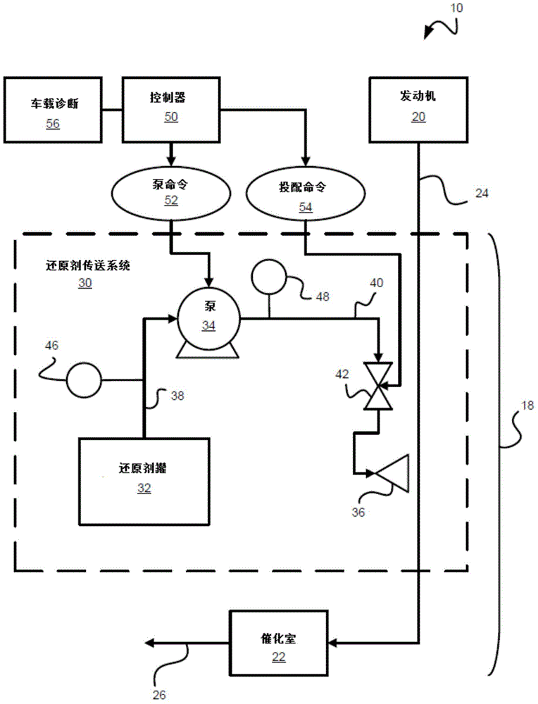
[0036] figure 1 One embodiment of an engine system 10 is shown. The major components of engine system 10 include internal combustion engine 20 and an exhaust aftertreatment system, which may be in the form of a selective catalytic reduction (SCR) system 18 including a catalytic chamber 22 in communication with internal combustion engine 20 And exhaust gas is received through exhaust line 24 . Catalytic chamber 22 includes any type of catalyst, such as an SCR catalyst, configured to interact with the exhaust and reduce NOx in the presence of ammonia. The internal combustion engine 20 may be a compression ignition engine, such as a diesel fueled engine, or a spark ignited internal combustion engine, such as a gasoline fueled engine operated on a tilt. Fuel and air are combusted within a compression chamber of internal combustion engine 20 to provide exhaust gas, which is discharged into exhaust line 24 . At least a portion of the exhaust flow flows from exhaust line 24 into o...


PUM


Abstract

An exhaust gas treatment system for an internal combustion engine may have a reductant delivery system with a reductant tank (32). A filter module (100) positioned in the reductant tank filters reductant before it is conveyed to the reductant pump (34) to remove impurities. In order to reduce gas flow to the pump (34), the filter module (100) may have an outlet port leading to the reductant pump (34) and a venting port (210) positioned above the outlet port (212) such that gas bubbles float to the venting port (210) prior to entry of the reductant into the outlet port (210). The filter module (100) may be secured to a tank level tank level sensor assembly (80), and may vent the gas to a gas reservoir (72) above the reductant in the reductant tank (32). Such a filtration system may operate independently of any return line that conveys reductant back to the reductant tank (32).

Description

technical field [0001] The present invention relates to internal combustion engines, and more particularly to filtration for reductant delivery systems for exhaust aftertreatment. Background technique [0002] In recent years, emission regulations for internal combustion engines have become more stringent. Concern for the environment has led to stricter emission regulations for internal combustion engines in most parts of the world. Government agencies, such as the Environmental Protection Agency (EPA) in the United States, carefully monitor engine emissions and set appropriate emission standards with which all engines must comply. As a result, exhaust aftertreatment systems are increasingly being used on engines to reduce emissions. [0003] In general, emission regulations vary depending on the type of engine. Emissions tests for compression ignition (e.g. diesel) engines typically measure released carbon monoxide (CO), unburned hydrocarbons (UHC), engine particulate ma...

Claims


Application Information

Patent Timeline
IPC IPC(8): B01D35/02B01D29/56B01D19/02B01D53/94B01D53/56F01N3/28
CPCF01N2610/1426B01D35/30B01D19/0031F01N3/2066F01N2610/1466F01N3/08F01N2610/02Y02T10/12
Inventor A·迈尔J·海彻尔贝赫G·芒蒂恩S·霍尔J·伯克J·安西斯
Owner CUMMINS INTPROP INC
Why Eureka
Try Eureka