Hydrodynamic cavitation generating device

A generating device and hydraulic cavitation technology, applied in chemical instruments and methods, chemical/physical processes, chemical/physical/physical chemical processes, etc., can solve problems such as low efficiency and low hydraulic cavitation intensity, and achieve energy Low consumption, low cost and simple structure

Inactive Publication Date: 2014-09-17
TSINGHUA UNIV
View PDF0 Cites 13 Cited by
  • Summary
  • Abstract
  • Description
  • Claims
  • Application Information

AI Technical Summary

Problems solved by technology

Compared with ultrasonic cavitation, hydraulic cavitation has simple equipment and low cost, and can generate large-scale cavitation fields (such as orifice plates, Venturi tubes, liquid whistles, etc.), but the cavitation intensity of hydraulic cavitation is small. Less efficient, often insufficient for triggering or strengthening of certain physicochemical reactions

Method used


Image

  • Hydrodynamic cavitation generating device
  • Hydrodynamic cavitation generating device

Examples


Embodiment Construction

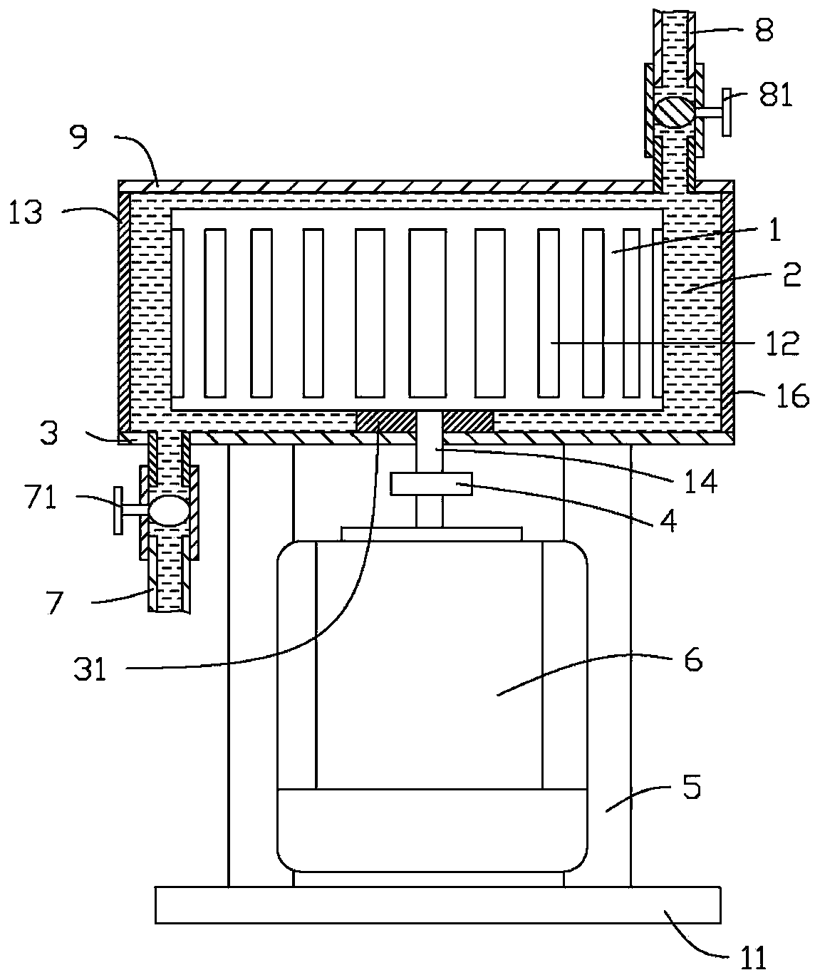
[0014] The hydraulic cavitation generating device provided by the present invention will be further described in detail below in conjunction with the accompanying drawings and specific embodiments.

[0015] See figure 1 with figure 2 , the embodiment of the present invention provides a hydraulic cavitation generating device 10, the hydraulic cavitation generating device 10 includes a support unit, a driving unit and a cavitation generating unit, the driving unit is arranged on the supporting unit, and the cavitation generating The unit is arranged on the supporting unit and driven by the driving unit.

[0016] The supporting unit includes a base 11 and a bracket 5 disposed on the base 11 . The drive unit includes a motor 6 and a shaft coupling 4 installed on the motor shaft. The motor 6 in the drive unit is mounted on the bracket 5 .

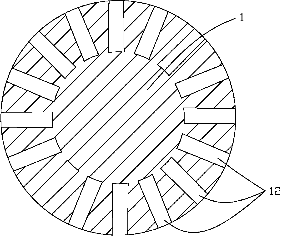
[0017] The cavitation generating unit includes a container 2, and the container 2 has a cavity inside. The container 2 is composed of a f...


PUM


Abstract

The invention relates to a hydrodynamic cavitation generating device which comprises a support unit, a driving unit and a cavitation generating unit, wherein the driving unit is arranged on the support unit; the cavitation generating unit is arranged on the support unit and driven by the driving unit; the cavitation generating unit comprises a container and a rotor, wherein a cavity is formed in the container, the rotor is a current limiting device and is arranged in the cavity, and the rotor can be driven to rotate by the driving unit.

Description

technical field [0001] The invention relates to a hydraulic cavitation generating device, in particular to a hydraulic cavitation generating device capable of generating hydraulic cavitation effects in a rotating flow-limiting manner and used for intensifying physical and chemical processes. Background technique [0002] Cavitation is a process in which vapor bubbles are formed in the low-pressure region of the liquid flow field. In some respects, cavitation is similar to boiling. The difference between the two is that boiling is mainly the result of temperature rise, while cavitation is the main cause. is a reduction in pressure. When the internal pressure of the liquid drops below the saturated vapor pressure (not necessarily exactly the same in the strict sense), the bubbles formed by the cavitation process begin to appear and grow, and as time goes on, the bubbles expand, grow, compress and collapse. But this process is explosive, less than six thousandths of a second, ...

Claims


Application Information

Patent Timeline
Patent Type & Authority Applications(China)
IPC IPC(8): B01J19/00
CPCB01J19/008B01J19/0066B01J19/1806B01J2219/00189F24V40/00
Inventor 周明张伟
Owner TSINGHUA UNIV
Why Eureka
Try Eureka