Copper bar bending device

A technology of bending device and bending mechanism, which is applied in the fields of manual bending device for metal pipes and manual bending and forming of copper bars for turbine generator rotors, which can solve the problems of high equipment cost, large bending resistance, and easy Wrinkle and other problems, to achieve high processing efficiency, low bending resistance, avoid wrinkling and thickening out of tolerance

Active Publication Date: 2014-09-17
ZHENJIANG ZHONGCHUAN XIANDAI GENERATING EQUIP CO LTD
View PDF6 Cites 6 Cited by
  • Summary
  • Abstract
  • Description
  • Claims
  • Application Information

AI Technical Summary

Problems solved by technology

At present, the copper bars of the rotor winding of the turbogenerator are usually bent by a special bending machine, the bending resistance is large, and the copper bars are easy to wrinkle at the bends, thicken and out of tolerance
And the operation is cumbersome, the equipment cost is high, suitable for mass production, not suitable for single piece or small batch production

Method used


Image

  • Copper bar bending device
  • Copper bar bending device
  • Copper bar bending device

Examples


Embodiment Construction

[0018] The present invention will be further described below in conjunction with drawings and embodiments.

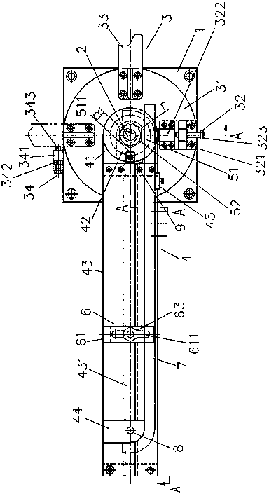
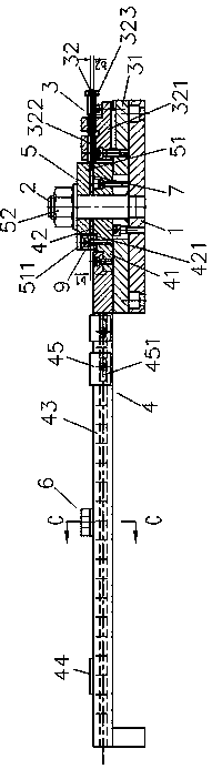
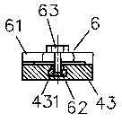
[0019] Such as figure 1 , figure 2 and image 3 As shown, the present invention includes a bottom plate 1 fixed on the workbench by fasteners, a main shaft 2 vertically welded and fixed in the middle of the bottom plate 1, a copper bar bending mechanism 3 sequentially fitted on the main shaft from bottom to top, and copper bar positioning Mechanism 4, locking mechanism 5 and copper bar pressing mechanism 6; copper bar bending mechanism 3 includes a rotating disc 31, a wire crimping device 32, a handle 33 and a handle limiter 34, the rotating disc 31 is set on the main shaft 2, and It can rotate freely around the main shaft 2. The center line of the thread crimping device 32 and the axis of the handle 33 are perpendicular to each other, and are respectively fixed on the radially outer sides of the rotating disk 31 by fasteners. The handle limiter 34 is located on th...


PUM


Abstract

The invention discloses a copper bar bending device. The copper bar bending device comprises a base plate, a main shaft, a copper bar bending mechanism, a copper bar locating mechanism, a locking mechanism and a copper bar pressing mechanism. The copper bar bending mechanism comprises a rotating disk, a wire pressing device, a handle and a handle limiting device, wherein the rotating disk is arranged on the main shaft in a sleeved mode, the wire pressing device and the handle are fixed to the radial outer side of the rotating disk, and the handle limiting device is fixed to the base plate. The copper bar locating mechanism comprises a backing plate, a core plate and a guide rail, wherein the backing plate and the core plate are sequentially arranged on the main shaft in a sleeved mode, a copper bar to be bent is longitudinally supported by the guide rail and one side of the backing plate, the inner side of one end of the copper bar to be bent abuts against one side of the core plate, and one end of the wire pressing device abuts against the outer side of one end of the copper bar to be bent. The copper bar pressing mechanism comprises an L-shaped pressing plate, a T-shaped nut and a pressing bolt. The locking mechanism comprises an upper pressing block and a locking nut. The copper bar bending device saves time and labor when operated, and is high in machining efficiency, low in cost, small in bending resistance in the bending process and suitable for single-piece or small-scale production.

Description

technical field [0001] The invention relates to a manual bending device for metal pipes, in particular to a device suitable for manual bending and forming of copper bars of turbine generator rotors, and belongs to the technical field of pressure bending forming machinery. Background technique [0002] The rotor winding of the turbogenerator is made of copper bars with a large width-thickness ratio, and the two ends of the copper bars need to be bent at 90° angles respectively. At present, the copper bars of the rotor windings of the turbogenerator are usually bent by a special bending machine, which has a large bending resistance, and the copper bars are prone to wrinkling, thickening and out-of-tolerance. And the operation is cumbersome, the equipment cost is high, suitable for mass production, not suitable for single piece or small batch production. Contents of the invention [0003] The object of the present invention is to provide a copper bar bending device suitable ...

Claims


Application Information

Patent Timeline
Patent Type & Authority Applications(China)
IPC IPC(8): B21D7/00
Inventor 王明甘佐军
Owner ZHENJIANG ZHONGCHUAN XIANDAI GENERATING EQUIP CO LTD
Why Eureka
Try Eureka