
Lifting device for onboard optoelectronic platform

A lifting device and photoelectric platform technology, which is applied in the field of aviation optoelectronics, can solve the problems of poor rigid connection and unstable structure of the lifting device, etc., and achieve the effect of local rigidity enhancement, simple structure and high rigidity

Inactive Publication Date: 2014-09-17
CHANGCHUN INST OF OPTICS FINE MECHANICS & PHYSICS CHINESE ACAD OF SCI
View PDF3 Cites 11 Cited by
  • Summary
  • Abstract
  • Description
  • Claims
  • Application Information

AI Technical Summary

Problems solved by technology

[0004] The purpose of the present invention is to provide a kind of lifting device for airborne optoelectronic platform in order to solve the problem of unstable structure and poor rigid connection of the existing lifting device for airborne optoelectronic platform

Method used


Image

  • Lifting device for onboard optoelectronic platform

Examples


Embodiment Construction

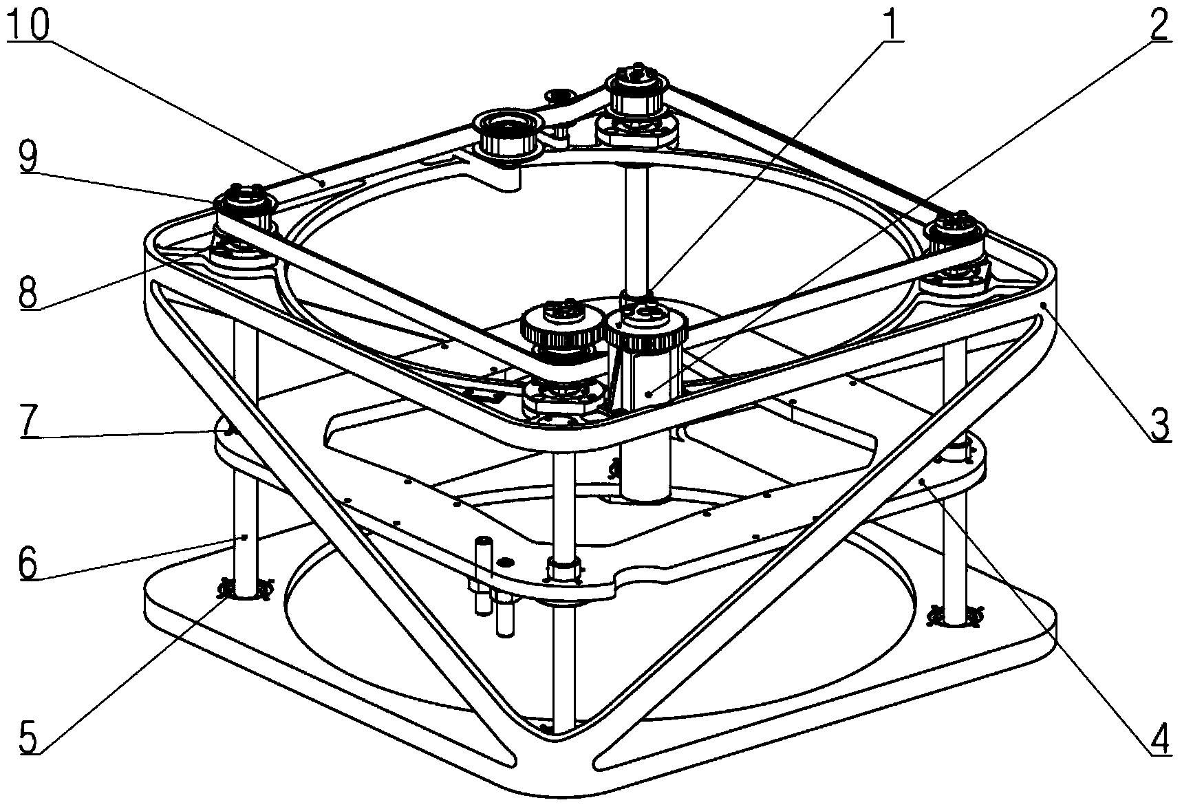
[0013] A lifting device for an airborne optoelectronic platform described in this embodiment, such as figure 1 As shown, the device includes a gear set 1, a motor 2, a base body 3, a lifting plate 4, four first bearing housing components 5, four lead screws 6, nuts 7, four second bearing housing components 8, four teeth belt pulley 9 and toothed synchronous belt 10, the base body 3 is an integrated structure, the four lead screws 6 pass through the lower end of the base body 3, and the lifting plate 4 passes through the upper end of the base body 3, and the gear set 1 includes driving gears And driven gear, described motor 2 is arranged on the base body 3, and driving gear is arranged on the motor shaft of motor 2, and driven gear is connected with a leading screw in four leading screws 6, and four toothed belt pulleys 9 are respectively connected to the upper ends of the four lead screws 6, and the toothed synchronous belt 10 is set on the four toothed pulleys 9. When the mot...


PUM


Abstract

The invention provides a lifting device for an onboard optoelectronic platform, belongs to the technical field of aviation optoelectronics, and solves the problems of unstable structure and poor rigid connectivity of the existing lifting device for the onboard optoelectronic platform. The device comprises a gear bank, a motor, a substrate, a lifting plate, four screws, four toothed belt wheels and a toothed synchronous belt, wherein the gear bank comprises a driving gear and a driven gear; the lifting plate is connected with the four screws; upper and lower ends of the four screws are connected with the substrate; the motor is installed on the substrate; the driving gear is arranged on the motor; the driven gear is connected with one of the four screws; the toothed belt wheels are connected with the upper ends of the screws; the toothed synchronous belt is wound on the four toothed belt wheels; when the motor is operated, the driven gear drives one of the four screws to rotate, then the toothed synchronous belt drives the four toothed belt wheels to rotate synchronously, and the rotation movement of the four screws is changed into up-and-down movement of the lifting plate. The lifting device disclosed by the invention is compact in structure, easy to install and stable.

Description

technical field [0001] The invention belongs to the technical field of aviation optoelectronics, and in particular relates to a lifting device for an airborne optoelectronic platform. Background technique [0002] The airborne optoelectronic platform is the most commonly used cutting-edge technology in modern weapon systems in the field of space optoelectronics, and is mainly used in aerial reconnaissance systems. In order to reduce wind resistance and protect the platform, some photoelectric platforms are equipped with a lifting mechanism to ensure that the photoelectric platform can rise and fall freely inside and outside the belly. [0003] Due to the limitation of volume and weight, the miniaturization, light weight and high rigidity of the lifting mechanism are always the main issues considered by designers. In the prior art, most of the lifting mechanisms used for airborne optoelectronic platforms adopt the upper, middle and lower three-layer plate structure to achiev...

Claims


Application Information

Patent Timeline
Patent Type & Authority Applications(China)
IPC IPC(8): B64D47/00
Inventor 李明王平李永刚刘仲宇程志峰
Owner CHANGCHUN INST OF OPTICS FINE MECHANICS & PHYSICS CHINESE ACAD OF SCI
Learn More