
Double stage compressor cylinder and double stage compressor possessing it

A two-stage compressor and cylinder technology, applied in the field of compressors, can solve problems such as unfavorable medium-pressure circulation channel design and affecting compressor performance, and achieve the effect of improving performance and optimizing positional relationship

Inactive Publication Date: 2014-09-17
ZHUHAI GREE REFRIGERATION TECH CENT OF ENERGY SAVING & ENVIRONMENTAL PROTECTION
View PDF5 Cites 2 Cited by
  • Summary
  • Abstract
  • Description
  • Claims
  • Application Information

AI Technical Summary

Problems solved by technology

Generally, the assembly holes are evenly distributed on the cylinder, which is beneficial to the sealing of the parts, reducing the deformation of the parts, and improving the reliability of the compressor. However, the evenly distributed assembly holes will not be conducive to the design of the medium pressure circulation channel, thus affecting the compression. machine performance

Method used


Image

  • Double stage compressor cylinder and double stage compressor possessing it
  • Double stage compressor cylinder and double stage compressor possessing it

Examples


Embodiment approach 1

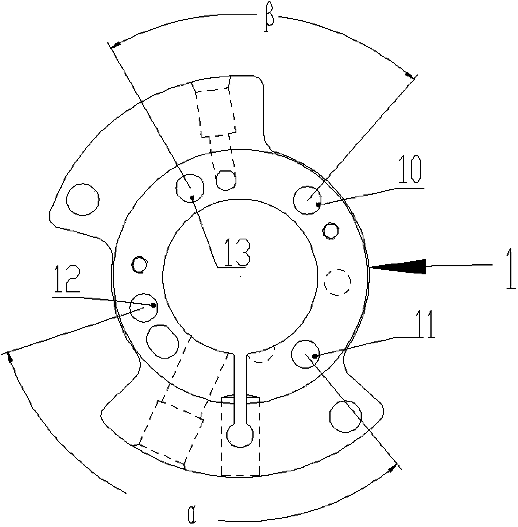
[0022] Such as figure 1 As shown, in order to facilitate the description of the problem, the present invention sets the assembly holes provided on the cylinder as four, that is, N=4, and the largest clip is formed between the adjacent second assembly holes 11 and the third assembly holes 12 on the cylinder 1. Angle α, the minimum angle β is formed between the adjacent first assembly hole 10 and the fourth assembly hole 13 on the cylinder 1. At this time, the maximum angle α, the minimum angle β and the total number of assembly holes N are according to the following relationship: α / (2π / N)0.4 are set, that is, α36°, which ensures that the sealing and deformation of the two-stage compressor are within a reliable range.

[0023] As a preferred embodiment, in the present invention, the maximum included angle α, the minimum included angle β and the total number of assembly holes N are designed according to the following relationship: α / (2π / N)0.5 , that is, when α45°, the distributi...

Embodiment approach 2

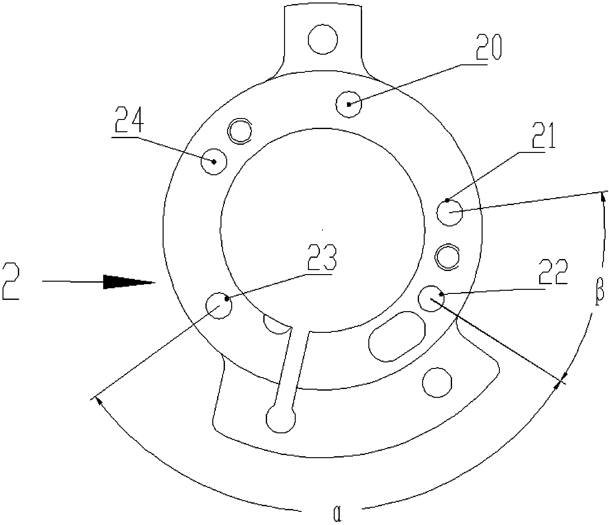
[0028] Such as figure 2 As shown, in this implementation, 5 assembly holes are designed on the cylinder 2, and the rest are the same as in Embodiment 1. This embodiment focuses on the differences from Embodiment 1, and the similarities will not be repeated.

[0029] The largest angle α is formed between the adjacent third assembly hole 22 and the fourth assembly hole 23 on the cylinder 2, and the minimum angle β is formed between the adjacent second assembly hole 21 and the third assembly hole 22 on the cylinder 2 , the adjacent first assembly hole 20 and the fifth assembly hole 24 are disposed close to the second assembly hole 21 and the fourth assembly hole 23 respectively. At this time, the maximum included angle α, the minimum included angle β and the total number of assembly holes N are set according to the following relationship: α / (2π / N)0.4, that is, α28.8° ensures that the sealing and deformation of the two-stage compressor are within a reliable range.

[0030] As a ...


PUM


Abstract

The invention provides a double stage compressor cylinder and a double stage compressor possessing it. The cylinder is provided with N assembling holes used for assembling, a largest angle between adjacent assembling holes is alpha, a smallest angle between the adjacent assembling holes is beta, the largest angle alpha, the smallest angle beta and the total number N of the assembling holes meet formulas of alpha / (2phi / N)<2 and beta / (2phi / N)>0.4, and the total number N of the assembling holes is not lower than 4. The double stage compressor cylinder allowing the positions of the assembling holes distributed on the cylinder to be reasonably arranged guarantees the sealing and deformation of the compressor in a reliable range, optimizes the design of a medium pressure circulation channel and improves the performance of the double stage compressor.

Description

technical field [0001] The invention relates to the field of compressors, more specifically, to a cylinder block of a two-stage compressor and a two-stage compressor with the same. Background technique [0002] When the two-stage compressor is working, the refrigerant enters the low-pressure stage cylinder for primary compression, and after being discharged, it is mixed with medium-pressure supplementary air and enters the high-pressure stage cylinder for secondary compression to complete the entire compression cycle. The medium-pressure circulation channel from the low-pressure stage exhaust to the high-pressure stage suction is an important part of the two-stage compressor. In order to reduce the resistance loss of the medium-pressure flow and improve the performance of the compressor, it is necessary to shorten the length of the medium-pressure flow channel and increase the flow rate. area. [0003] In the prior art, the medium-pressure flow channel of the two-stage comp...

Claims


Application Information

Patent Timeline
Patent Type & Authority Applications(China)
IPC IPC(8): F04C29/00
Inventor 黄辉胡余生魏会军
Owner ZHUHAI GREE REFRIGERATION TECH CENT OF ENERGY SAVING & ENVIRONMENTAL PROTECTION
Learn More