Heat pipe type solar vacuum tube water boiler and water boiling system

A technology of boiling water system and vacuum tube, which is applied in the field of heat pipe type solar vacuum tube water boiler and boiling water system, can solve the problem of difficulty in meeting the requirements of medium temperature, and achieve the effects of reducing sensible heat, easy installation and maintenance, and high reliability

Active Publication Date: 2014-09-17
浙江毕星新能源科技有限公司 +1
View PDF6 Cites 3 Cited by
  • Summary
  • Abstract
  • Description
  • Claims
  • Application Information

AI Technical Summary

Problems solved by technology

In addition, most of the hot water temperature that ordinary heat pipe vacuum tube collectors can provide cannot meet the requirements of medium temperature.

Method used


Image

  • Heat pipe type solar vacuum tube water boiler and water boiling system
  • Heat pipe type solar vacuum tube water boiler and water boiling system
  • Heat pipe type solar vacuum tube water boiler and water boiling system

Examples


Embodiment 1

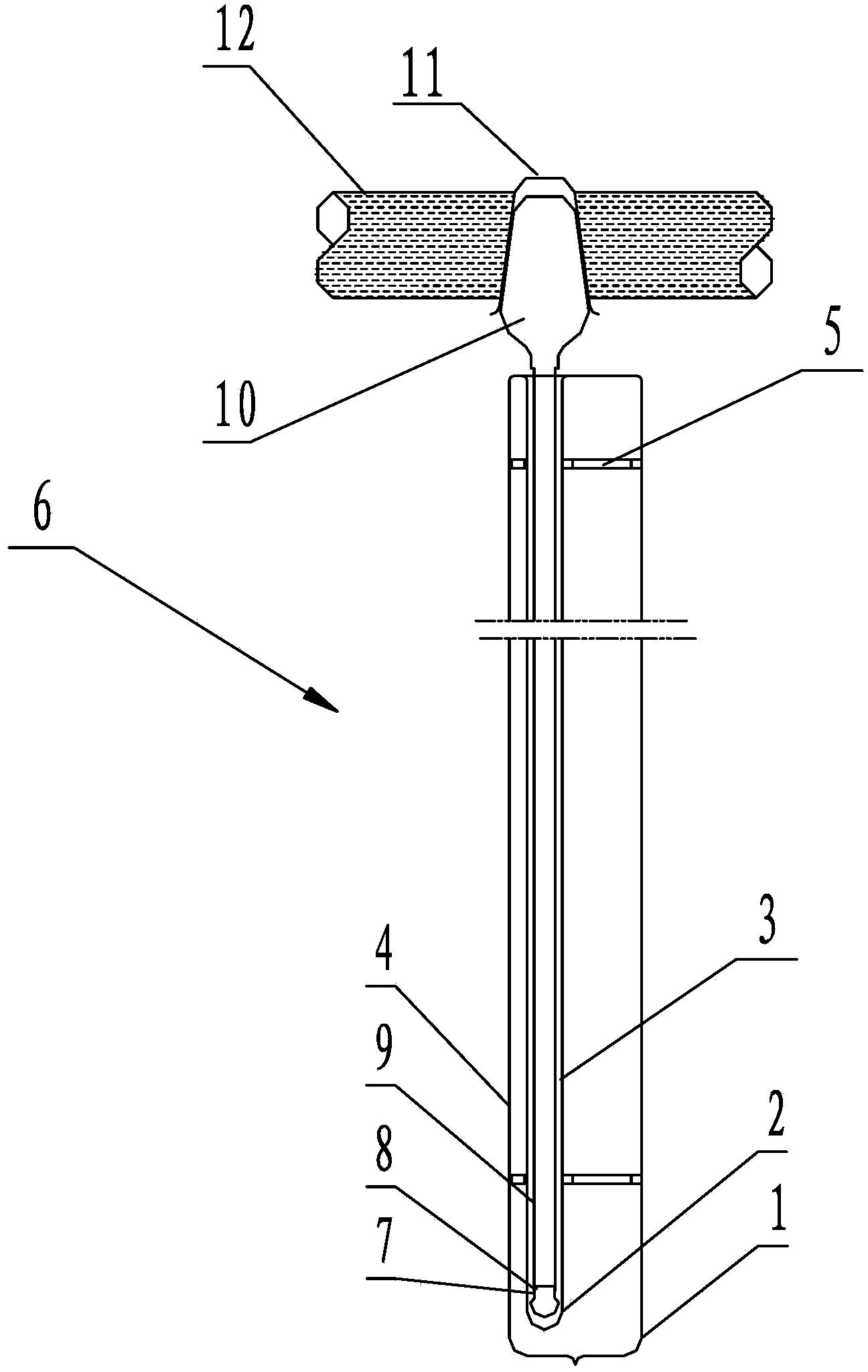
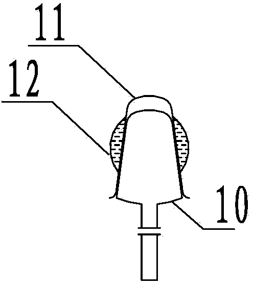
[0028] A heat pipe type solar vacuum tube water boiler, comprising 21 heat collecting single pipes 6 and a heat conduction pipe 12 connecting each heat collecting single pipe;

[0029] The heat-collecting single tube 6 includes an outer cover glass tube 1, a heated glass tube 2 arranged in the inner cavity of the outer cover glass tube 1, and a metal vacuum tube 9 inserted in the heated glass tube 2. The heated glass tube 2 and the outer cover glass tube 1 parallel, and the heated glass tube 2 is set off-axis in the outer cover glass tube 1 through the metal bracket 5, the outer wall of the heated glass tube 2 is kept separated from the inner wall of the outer cover glass tube 1, and is close to the outer cover glass tube 1 of the heated glass tube 2 Half of the inner wall is coated with metal reflective coating 4;

[0030] One end of the metal vacuum tube 9 located in the heated glass tube 2 is closed by a heat pipe pin 8 to fix the heat pipe plug 7, and the other exposed end...

Embodiment 2

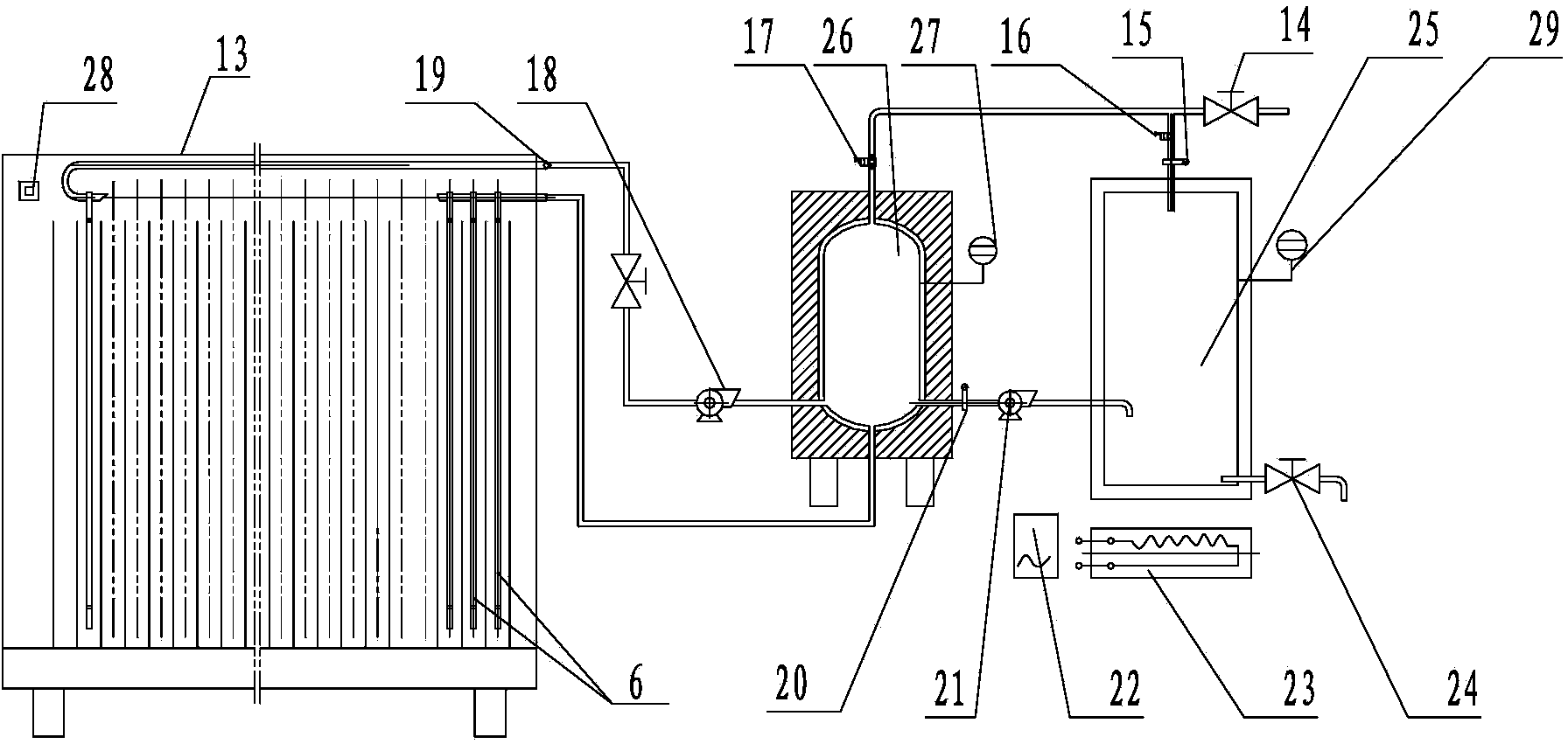
[0035] A heat pipe type solar vacuum tube water boiling system, comprising the heat pipe type solar vacuum tube water boiler described in embodiment 1, an electric heating type water boiler 25, a hot water storage tank 26, the two ends of the heat pipe 12 of the heat pipe type solar vacuum tube water boiler and the storage tank respectively The hot water inlet of the hot water tank 26 is connected to the water return port, and the hot water storage tank 26 is also provided with a cold water inlet and a water outlet connected to the hot water inlet of the electric water boiler 25 .

[0036] The heat pipe type solar vacuum tube water boiler is provided with a heat collector 13 outside, on which a photosensitive sensor 28 with a photovoltaic panel is installed.

[0037] One end of the heat conducting pipe 12 connected to the water return port of the heat storage tank 26 is provided with a water inlet check valve 19 . The water return port of the hot water storage tank 26 is provi...


PUM


Abstract

The invention discloses a heat pipe type solar vacuum tube water boiler and a water boiling system. The water boiler comprises a plurality of single connector tubes and a heat conduction water pipe connected with the single connector tubes; each single connector tube comprises an outer glass tube, a heated glass tube and a metal vacuum tube; each heated glass tube is arranged in the corresponding outer glass tube through a metal bracket in the manner of deviating from the axis; a metal reflective coating is plated on the inner wall of a half side of each outer glass tube close to the corresponding heated glass tube; one end, positioned in each heated glass tube, of the corresponding metal vacuum tube is closed through fixing a heat pipe seal head with a heat pipe pin, and the other end, which is exposed, of each metal vacuum tube extends outwards and is expanded to form a heat pipe seal head with a closed tail end and taking the shape of a cone frustum; a plurality of groove-shaped seal head taper sleeves are arranged on the heat conduction water pipe in an equally-spaced manner; each seal head taper sleeve takes the shape of an inverted cone frustum; the heat pipe seal heads are inserted in the seal head taper sleeves. Through the use of an all-glass internal light-focusing eccentric vacuum tube structure and other structures, heat is collected efficiently, high-temperature boiled water is produced continuously, the structure is simple, and the mass production is facilitated.

Description

technical field [0001] The invention relates to the technical field of solar vacuum tube heat collection, in particular to a heat pipe type solar vacuum tube water boiler and a water boiling system. Background technique [0002] In the current market, the ordinary solar water heaters of low-temperature solar products with a water temperature of less than 80°C and the large parabolic concentrating collectors of solar high-temperature products (heat medium temperature higher than 200°C) are very mature, but due to Due to its structure and cost factors, it cannot be widely used in the solar medium temperature heat collection market. [0003] Since the hot water of ordinary solar water heaters can only reach about 80°C in summer, and it can only be used for bathing or industrial purposes, and cannot be used for human consumption, the use of solar thermal resources in vast public buildings is in a dilemma: if using Building a solar photovoltaic power station system on the roof o...

Claims


Application Information

Patent Timeline
Patent Type & Authority Applications(China)
IPC IPC(8): F24J2/32F24J2/05F24J2/46F24J2/40F24S10/40F24S10/95
CPCY02E10/44
Inventor 殷明陈勇
Owner 浙江毕星新能源科技有限公司
Why Eureka
Try Eureka