Absolute calibration device and method for radio telescope antenna surface type

A technology for radio telescopes and antenna surfaces, applied to measuring devices, optical devices, instruments, etc., can solve problems such as being easily affected by ambient background light, poor anti-interference ability, high cost, etc., to ensure performance and reduce labor intensity , Easy assembly and debugging

Inactive Publication Date: 2014-09-17
NANJING INST OF ASTRONOMICAL OPTICS & TECH NAT ASTRONOMICAL OBSE
View PDF4 Cites 14 Cited by
  • Summary
  • Abstract
  • Description
  • Claims
  • Application Information

AI Technical Summary

Problems solved by technology

[0007] In order to overcome the disadvantages of low precision, poor anti-interference ability, or high cost, not real-time and heavy, and easily affected by ambient background light in the prior art methods for detecting and adjusting the reflecting surface of the above-mentioned antenna, the present invention aims at the main antenna

Method used


Image

  • Absolute calibration device and method for radio telescope antenna surface type
  • Absolute calibration device and method for radio telescope antenna surface type

Examples


Embodiment 1

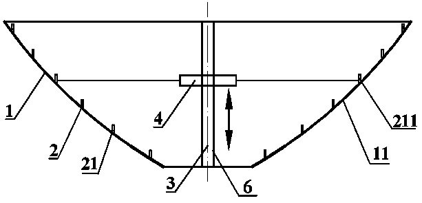
[0032] Such as figure 1 As shown, an absolute calibration device for the antenna shape of a radio telescope is composed of a PSD position sensor array 20, a linear guide 3, a ring laser 4 and a control circuit (not shown in the figure). The PSD position sensor array 20 consists of a number of coaxial The PSD position sensor circle 21 is composed of a linear guide 3 located at the central axis 6 of the main reflecting surface. Each PSD position sensor circle 21 is composed of several PSD position sensor units 211 with the linear guide 3 as the center and the photosensitive surface parallel to the central axis 6 The linear guide 3 is provided with a ring laser 4, the emitting surface of the ring laser 4 is perpendicular to the central axis 6; the control circuit is used to control the PSD position sensor 211 and the ring laser 4 for signal acquisition and signal processing.

[0033] On the main reflecting surface 1 composed of a large number of panels spliced, the PSD positio...

Embodiment 2

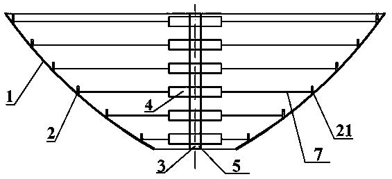
[0042] Such as figure 2 As shown, the difference between this embodiment and the previous example is that the central axis 6 is provided with a support shaft 5, and the support shaft 5 is provided with six ring lasers 4 along the height direction. Each ring laser 4 corresponds to a PSD position sensor ring 21. .

[0043] On the main reflecting surface 1 composed of a large number of panels 11 spliced ​​together, the PSD position sensor unit 211 is placed on the contour circles along the central axis 6 at the position to be measured. The PSD position sensor unit 211 contains PSD, The supporting mechanism and packaging have a highly consistent structural size and installation and positioning interface, and the zero-crossing point is uniformly calibrated in the laboratory, and on the fixed support shaft 5 at a fixed position parallel to the central axis of the main reflecting surface, how accurate is the installation A fixable ring laser 4, through the surface shape formula of the...


PUM


Abstract

The invention relates to an absolute calibration device and method for a radio telescope antenna surface type. The absolute calibration device for the radio telescope antenna surface type is composed of a PSD position sensor array, a supporting shaft, annular laser devices and a control circuit. The PSD position sensor array is composed of multiple coaxial PSD position sensor coils, each PSD position sensor coil is composed of multiple PSD position sensor units with multiple position points on a central axis as circle centers, and the photosensitive surfaces are dead against the central axis and are in parallel with the central axis. The supporting shaft is arranged on the central axis and provided with the annular laser devices, and the emitting surfaces of the annular laser devices are perpendicular to the central axis. The device is simple in structure, low in cost and easy to manufacture and assemble. The active reflecting surfaces of the radio telescope are convenient to upgrade, performance of the radio telescope is guaranteed in real time, and the implementation technology is simple.

Description

Technical field [0001] The invention relates to a radio telescope antenna face shape absolute calibration device and method based on a ring laser and a PSD array, which is very suitable for the absolute splicing calibration detection and correction of the radio panel of the radio telescope. Background technique [0002] Radio telescopes usually have a large aperture, and their antennas (main panels) are usually made up of large quantities of small panels. For example, a 65-meter-aperture radio telescope antenna is composed of thousands of panels on the order of one meter. The radio telescope is installed and In the process of putting it into official operation, under the influence of external loads such as gravity and wind, it is necessary to ensure that the overall shape of the paraboloid is within the allowable range. In addition to considering the support and shape-preserving design of the antenna back frame, the large-scale panel splicing inspection is also a key part of the ...

Claims


Application Information

Patent Timeline
IPC IPC(8): G01B11/245
Inventor 张勇李烨平
Owner NANJING INST OF ASTRONOMICAL OPTICS & TECH NAT ASTRONOMICAL OBSE
Why Eureka
Try Eureka