
High-overload-resistant structure protecting pressure/differential-pressure transmitters
A differential pressure transmitter, high-resistant technology, applied in the direction of measuring fluid pressure, instruments, measuring devices, etc., can solve problems such as damage to single crystal silicon
- Summary
- Abstract
- Description
- Claims
- Application Information
AI Technical Summary
Problems solved by technology
Method used
Image

Examples
Embodiment 1
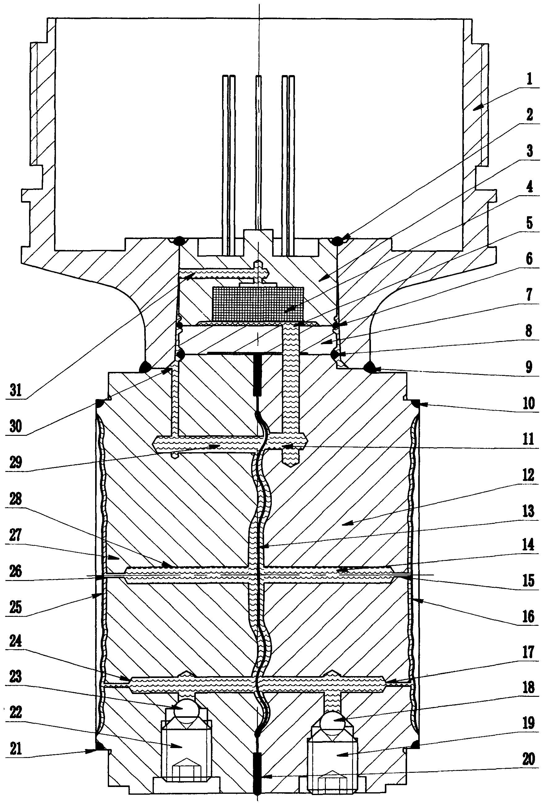
[0018] There is a pair of positive pressure side base 12 and negative pressure side base 27 arranged together. A central diaphragm 13 is arranged between the inner end corrugated surfaces of the positive pressure side base and the negative pressure side base. The upper and lower corrugated outer peripheries of the inner ends of the base on the pressure side and the base on the negative pressure side are fixed together, the upper ends of the base on the positive pressure side and the base on the negative pressure side are fixed with a connecting piece 1, and the positive pressure side A cushion block 7 is arranged at the middle upper end of the base and the negative pressure side base, a silicon sensor 3 is fixed on the upper end of the cushion block, and a silicon chip 4 is arranged at the center of the lower end of the silicon sensor; a positive pressure side is arranged at the center of the positive pressure side base and the cushion block. The pressure introduction hole 5, t...
PUM
 Abstract
Description
Claims
Application Information