
High-temperature-resistant release film

A release film, high temperature resistant technology, applied in the direction of layered products, synthetic resin layered products, chemical instruments and methods, etc., can solve the problems of poor operation convenience, strong adhesion, poor antistatic performance, etc., to achieve high Heat resistance, effect of blocking heat transfer

Pending Publication Date: 2020-12-01
凯仁精密材料(江苏)有限公司
View PDF4 Cites 0 Cited by
  • Summary
  • Abstract
  • Description
  • Claims
  • Application Information

AI Technical Summary

Problems solved by technology

[0003] The existing release film is mainly coated with a release layer on the substrate layer, but there are the following problems: PET / PE release film is generally used as a raw material for other products, and for some products, its strength is low and stable. The problems of poor performance and poor antistatic performance; after the existing release film is used, when the release film needs to be separated, it is generally separated directly from the corner of the release film, but the size of the release film is very thin , the gap between other films and the release film is small, and the adhesion between the two is relatively large. When the release film is torn off from other films, it is prone to damage or incomplete tearing, which is difficult to operate. Start, making the operation less convenient
[0005] However, although the above-mentioned release film has a certain flame-retardant performance, it cannot control the heat transfer in the external combustion environment, and the heat is easily transferred through the release film, which will damage the film-coated product and bring economic losses to the enterprise.

Method used


Image

  • High-temperature-resistant release film
  • High-temperature-resistant release film
  • High-temperature-resistant release film

Examples


Embodiment Construction

[0028] The specific implementation manner of the present invention will be further described below in conjunction with the accompanying drawings and embodiments.

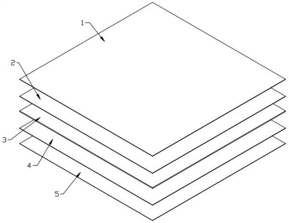
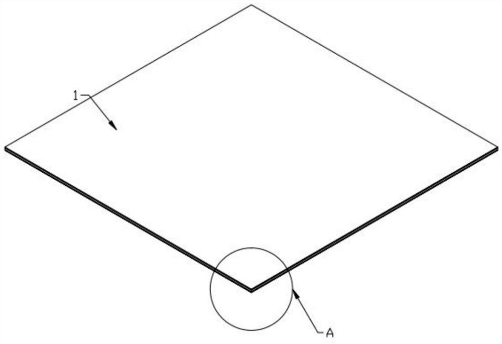
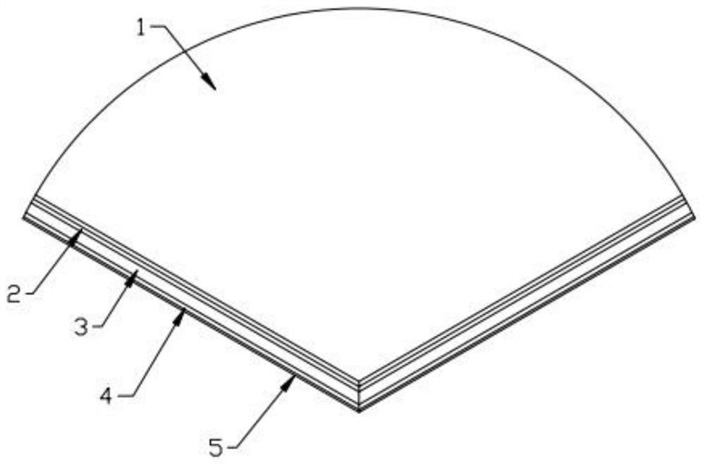
[0029] Such as Figures 1 to 5 As shown, the high temperature resistant release film includes a base layer 4, one side of the base layer 4 is provided with a release agent coating 5, and the other side of the base layer 4 is provided with a heat insulation layer 3, and the heat insulation layer 3 is away from the base layer 4 One side of the heat-resistant layer 2 is provided with a flame-retardant layer 1 on the side away from the heat-insulation layer 3; the interior of the heat-insulation layer 3 is provided with a vacuum interlayer 305; in this embodiment, The flame retardant layer 1 has the property of being non-combustible. By setting the flame retardant layer 1 on the outermost layer of the release film, the flame retardant layer 1 makes the release film difficult to burn; the anti-heat layer 2 has a high ref...


PUM

PropertyMeasurementUnit
Thicknessaaaaaaaaaa
Heightaaaaaaaaaa
Diameteraaaaaaaaaa

Abstract

The invention provides a high-temperature-resistant release film which comprises a base layer, a release agent coating is arranged on one side of the base layer, a heat insulation layer is arranged onthe other side of the base layer, a heat reflection layer is arranged on the side, deviating from the base layer, of the heat insulation layer, a flame-retardant layer is arranged on the side, deviating from the heat insulation layer, of the heat reflection layer, a vacuum interlayer is arranged in the heat insulation layer, the surface layer of the release film is not prone to combustion and hascertain flame retardance, the release film has high heat resistance by means of heat reflection and heat isolation, heat transfer from one side to the other side can be effectively controlled and reduced, and a film-coated product is effectively protected.

Description

technical field [0001] The invention belongs to the technical field of release films, and in particular relates to a high-temperature-resistant release film. Background technique [0002] The release film refers to a film whose surface can be distinguished. The release film is not sticky or slightly sticky after contacting with a specific material under limited conditions. [0003] The existing release film is mainly coated with a release layer on the substrate layer, but there are the following problems: PET / PE release film is generally used as a raw material for other products, and for some products, its strength is low and stable. Poor performance and poor antistatic performance; After the existing release film is used, when the release film needs to be separated, it is generally separated directly from the corner of the release film, but the size of the release film is very thin , the gap between other films and the release film is small, and the adhesion between the tw...

Claims


Application Information

Patent Timeline
IPC IPC(8): B32B33/00B32B27/06B32B27/36
CPCB32B33/00B32B27/365B32B27/06B32B27/36B32B2307/3065B32B2307/306
Inventor 余国良
Owner 凯仁精密材料(江苏)有限公司
Learn More