Environmental protective automatic continuous paraffin-embedding device

A paraffin embedding and automatic technology, applied in the preparation of test samples, etc., can solve the problems of inconvenience and single function, and achieve the effect of reducing work trouble, convenient observation and safe use

Active Publication Date: 2014-09-17
SHENYANG YUDE ELECTRONICS INSTR
View PDF11 Cites 19 Cited by
  • Summary
  • Abstract
  • Description
  • Claims
  • Application Information

AI Technical Summary

Problems solved by technology

[0003] However, the currently used paraffin embedding machines usually have the disadvantage of single function, which brings some inconvenience to the units using paraffin embedding machines.

Method used


Image

  • Environmental protective automatic continuous paraffin-embedding device
  • Environmental protective automatic continuous paraffin-embedding device
  • Environmental protective automatic continuous paraffin-embedding device

Examples


Embodiment 1

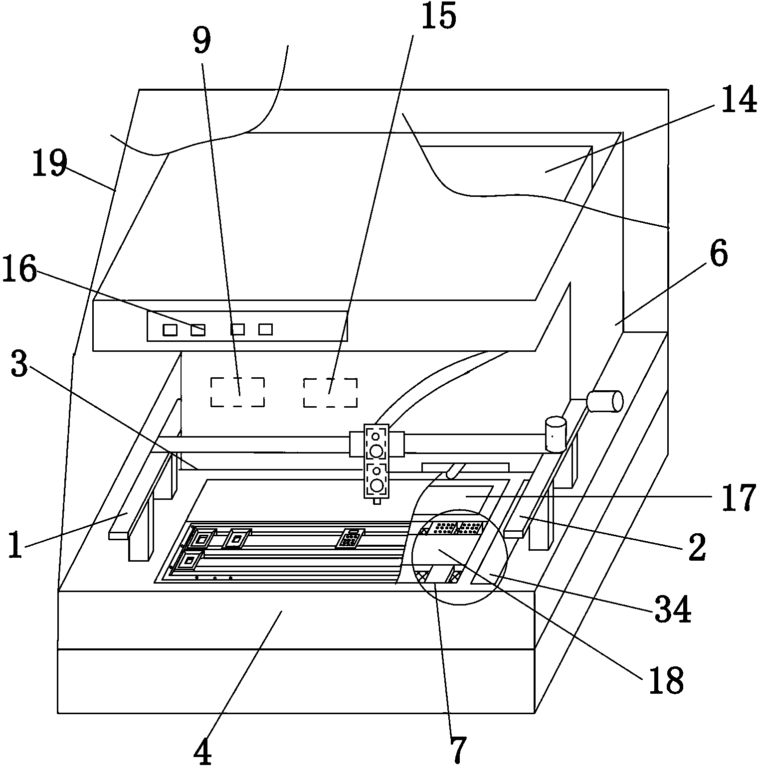
[0041] The environment-friendly automatic continuous paraffin embedding machine includes a housing 6 and a working table 4. The housing 6 is fixed on the workbench 4 .

[0042] A transmission device is provided on the workbench 4 , and the transmission device includes a first guide rail 1 , a second guide rail 2 and a third guide rail 3 . The first guide rail 1 and the second guide rail 2 are fixedly supported on the workbench 4 by two brackets respectively.

[0043] The first guide rail 1 and the second guide rail 2 with the same structure are respectively arranged on both sides of the workbench 4 and are parallel to each other. The two ends of the third guide rail 3 are fixed on the sliders of the first guide rail 1 and the second guide rail 2 respectively. The slider of the first guide rail 1 and the slider of the second guide rail 2 move synchronously.

[0044] A first installation slot 7 is opened on the workbench 4, and a wax box 18 and a cold box 17 are arranged in th...

Embodiment 2

[0058] Embodiment 2 is basically the same as Embodiment 1, and its difference is:

[0059] A telescopic device is also provided between the wax tube and the slider of the third guide rail 3 , and the telescopic device includes a chute 22 , an upper slider 23 and a lower slider 24 . The upper slider 23 and the lower slider 24 are installed in the chute 22, and the position is set up and down. Two chute positioning holes are provided on the chute 22, and two chute positioning holes are respectively opened on the upper slider 23 and the lower slider 24. Two upper positioning holes 25 and lower positioning holes 26, longitudinally offer two fixing holes on the slide block of the third guide rail 3, the positions of the chute positioning holes, the upper positioning holes 25, the lower positioning holes 26 and the fixing holes correspond to each other.

[0060] The upper positioning hole 25 of the fixing hole, the upper slide block and the chute positioning hole are fixedly assembl...

Embodiment 3

[0068] Embodiment 3 is basically the same as Embodiment 2, and its difference is:

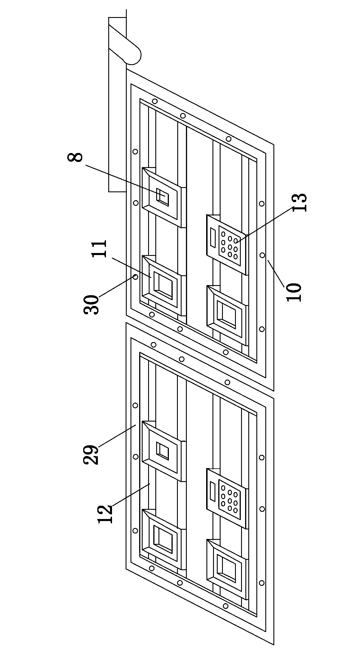
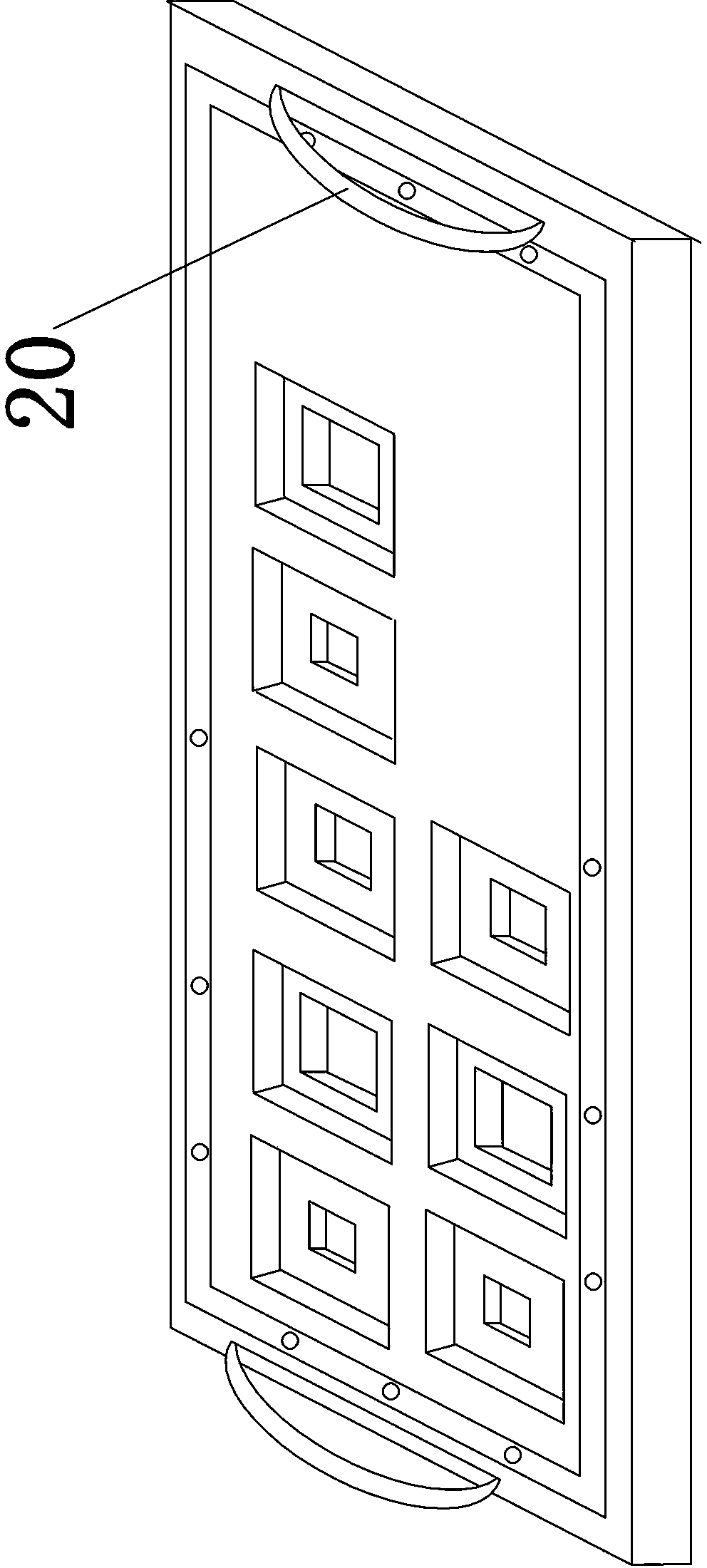
[0069] The embedding mold 11 and the embedding plate 10 are integrally designed. The embedding mold 11 is set on the embedding plate 10 and has an integrated structure with the embedding plate 10, and a wax groove 29 is set on the edge of the embedding plate 10, and a plurality of wax holes 30 are opened in the wax groove 29. (Such as image 3 shown). A cover plate may be provided on the heat tank 34 .

[0070] The heating device is a plurality of electric heating plates, and the plurality of electric heating plates are fixed on the outside of the bottom of the wax holding box 18 and the heat tank 34 . The electric heating plate is a known technology, so it will not be repeated.


PUM


Abstract

Disclosed is an environmental protective automatic continuous paraffin-embedding device which includes a shell body and a workbench, wherein the shell body and the workbench are fixedly connected to each other. The workbench is provided with three guide rails, wherein two guide rails are fixed on the workbench in parallel through two supports and two ends of the third guide rail are respectively arranged on the two guide rails. A first installation groove is formed in the workbench. A paraffin-accommodating box and a cooling box are arranged in the first installation groove. A heating apparatus is disposed on the exterior of the bottom of the paraffin- accommodating box and a filter screen is arranged in the paraffin-accommodating box. The cooling box refrigerates through a refrigerating apparatus. The first installation groove is provided with an embedding plate which is provided with an embedding mould and an embedding box. A paraffin box is arranged in the shell body. A stop valve and a paraffin pipe are disposed on the bottom of the paraffin box. An outlet of the paraffin pipe is arranged on a slide block of the third guide rail, is adjusted through a telescoping apparatus and sucks residual paraffin up through a paraffin-refluxing pipe. An unfolding bench and an organization box are arranged on the filter screen in the paraffin-containing box. The paraffin-embedding device can be used for manufacturing a plurality of paraffin embedding block, has complete functions, is safe and environment-friendly and is safe to use.

Description

Technical field [0001] The present invention belongs to the field of paraffin buried machines, which specially involves environmental protection automatic continuous paraffin embedded machines. Background technique [0002] Paraffects are buried in tissue wax blocks after dehydration and waxing of human or plant specimens for sections for tissue diagnosis or research.The use of animal and plant research units and food inspection departments. [0003] However, the current use of paraffin burying machines usually have a single disadvantage of a single function, which brings some inconvenience to the units using paraffin bag. [0004] Therefore, the present invention invented the environmental protection automatic paraffin embedded machine with embedded plates, tissue development platforms, residual wax storage recycling structures, and waxing waxes. Invention content [0005] The purpose of the present invention is to provide environmental protection automatic continuous paraffin ...

Claims


Application Information

Patent Timeline
Patent Type & Authority Applications(China)
IPC IPC(8): G01N1/36
Inventor 李朝林
Owner SHENYANG YUDE ELECTRONICS INSTR
Why Eureka
Try Eureka