Out-of-focus solar telescope guidscope based on pupil shield

A solar telescope and pupil occlusion technology, applied in the field of solar telescope guide mirrors, can solve problems such as difficult installation and processing adjustment, low anti-interference ability, complicated assembly, etc., to achieve convenient assembly and debugging, and facilitate mass production, production and assembly easy effect

Inactive Publication Date: 2014-09-17
NANJING INST OF ASTRONOMICAL OPTICS & TECH NAT ASTRONOMICAL OBSE
View PDF9 Cites 6 Cited by
  • Summary
  • Abstract
  • Description
  • Claims
  • Application Information

AI Technical Summary

Problems solved by technology

[0010] The technology of the present invention solves the problem: Aiming at various deficiencies in the prior art, the present invention proposes a new type of solar telescope guide mirror, which can overcome the low precision, low anti-interference ability, high cost, objective lens division and deflection of the prior art. The assembly of folding is relatively complicated, and installation, processing and adjustment are difficult. By blocking the pupil and using a small target camera and computer on the defocused image plane of the guide light path, the sun imaging, guide star detection and its feedback correction can be realized. Eliminates the selection, processing, installation and adjustment of split mirrors and optical wedge components, except for pupil occlusion and a lens component that can be added to adjust the focus, there is no need to control the follow-up guide light of the guide tube or the refractor of the main mirror tube Add any other components on the road, the structure is very simple, the use is very convenient, the cost is very low, and it is convenient for mass production

Method used


Image

  • Out-of-focus solar telescope guidscope based on pupil shield
  • Out-of-focus solar telescope guidscope based on pupil shield
  • Out-of-focus solar telescope guidscope based on pupil shield

Examples


Embodiment 1

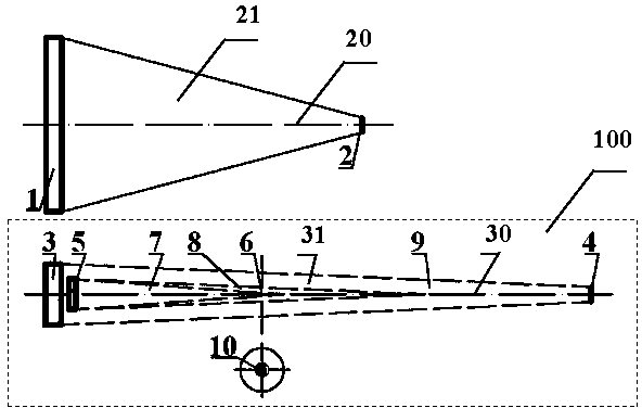
[0027] This embodiment is based on the guide star of the guide star barrel, such as figure 1 As shown, the defocused solar telescope guide mirror 100 based on pupil occlusion is composed of a guide star focusing lens 3 and a circular pupil occlusion 5 at the center of the guide star optical path optical axis 30 after the guide star focusing lens 3 .

[0028] The main mirror optical axis 20 is formed between the main mirror objective lens 1 and the main mirror focal point 2, and the guide star focusing lens 3 is installed on the guide star barrel parallel to the main mirror optical axis 20. The optical axis 20 of the optical path is parallel. On the optical axis 30 of the guide star optical path, the focus lens 3 of the guide mirror, the pupil block 5, the black area 7, the vignetting area 8, the imaging position 6 of the defocused camera, the bright area 9 and the focus 4 of the guide star focus lens are arranged in sequence. The defocused imaging image plane 10 at the defocu...

Embodiment 2

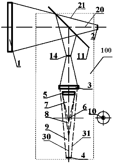
[0031] In this embodiment, the light path of the guide star mirror is refracted by the main mirror. Such as figure 2As shown, the main mirror optical path optical axis 20 is provided with a refractor 11, and the guide star optical path 31 is produced by refraction. The guide star lens guide star is set behind the conjugate point 14 of the main focus on the guide star optical path 31, and the guide star is set on the optical axis of the main mirror optical path. 20, the main mirror focus lens 1, the refractor 11 and the main mirror focus 2 are arranged in sequence. On the optical axis 30 of the guide star optical path, the refractor 11, the conjugate point 14 of the main focus, the focus lens 3 of the guide mirror, the pupil occlusion 5, the black area 7, the vignetting area 8, the defocused camera imaging position 6, and the bright The area 9 and the focal point 4 of the guide star focusing lens are arranged in sequence. The defocused imaging image plane 10 at the defocused...

Embodiment 3

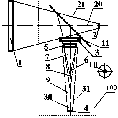
[0034] In this embodiment, the light path of the guide mirror is refracted by the main mirror. The difference between this embodiment and the previous example is that a guide lens is set before the conjugate point 14 of the main focus on the guide light path 31 . Such as image 3 As shown, the main mirror optical path optical axis 20 is provided with a refractor 11, and the guide star optical path 31 is produced by refraction. The guide star lens guide star is set behind the conjugate point 14 of the main focus on the guide star optical path 31, and the guide star is set on the optical axis of the main mirror optical path. 20, the main mirror objective lens 1, the refractor 11 and the main mirror focus 2 are arranged in sequence. On the optical axis 30 of the guide star optical path, refractor 11, guide star mirror focus lens 3 with optional adjustable focal length, pupil block 5, black area 7, vignetting area 8, defocused camera imaging position 6, bright area 9 and The foca...


PUM


Abstract

The invention discloses an out-of-focus solar telescope guidscope based on a pupil shield. According to the technical scheme, the pupil shield is installed in the center of a star guide optical axis in front or back of a guidscope focusing lens. By the utilization of the out-of-focus solar telescope guidscope based on the pupil shield, partition of mirror planes or machining, installation and adjustment of four optical wedges can be eliminated, and assembly and adjustment are extremely convenient.

Description

technical field [0001] The invention belongs to the field of photoelectric instruments, and specifically designs a solar telescope guide mirror based on blocking pupils and imaging on a defocused image plane of a guide light path. Background technique [0002] The solar telescope is a kind of astronomical telescope dedicated to observing the sun. The fundamental difference between the solar telescope and the night stellar telescope is that the observation target source is the sun with low-contrast extended source and the high-contrast target in night astronomy. In order to achieve telescope tracking and image stabilization, astronomical The guide star of the telescope is essential. As a high-brightness extended observation target source, the sun has an angular diameter of about 32 arc minutes, and the extended target features on the image of the sun present low contrast, for example, the diameter of sunspots on the photosphere reflecting solar activity is about 1 / 194 of that...

Claims


Application Information

Patent Timeline
Patent Type & Authority Applications(China)
IPC IPC(8): G02B23/00
Inventor 张勇李烨平曾裔中
Owner NANJING INST OF ASTRONOMICAL OPTICS & TECH NAT ASTRONOMICAL OBSE
Why Eureka
Try Eureka