Dynamic reactive power compensation device response time test method

A technology of compensation device and response time, which is applied in the direction of measuring device, measuring electricity, measuring electric variables, etc., can solve the problem that reactive output signal cannot be measured and recorded in real time, cannot effectively distinguish step response time and stabilization time, and cannot test step Issues such as response time and calm down time

Active Publication Date: 2014-09-17
STATE GRID CORP OF CHINA +2
View PDF6 Cites 24 Cited by
  • Summary
  • Abstract
  • Description
  • Claims
  • Application Information

AI Technical Summary

Problems solved by technology

[0005] The current waveform curve method is used to test the response time. Since the reactive output signal cannot be measured and recorded in real time, this method replaces the reactive signal with the current signal and ignores the change of the voltage signal during this period. It cannot accurately test the response time of the device, nor can it test Step response time and stabilization time, resulting in the inability to effectively distinguish between step response time and stabilization time in many occasions, resulting in deviations and misunderstandings in the understanding of these two concepts

Method used


Image

  • Dynamic reactive power compensation device response time test method
  • Dynamic reactive power compensation device response time test method
  • Dynamic reactive power compensation device response time test method

Examples


Embodiment Construction

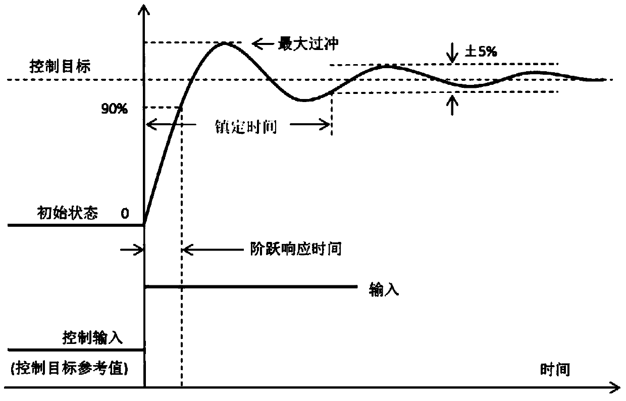
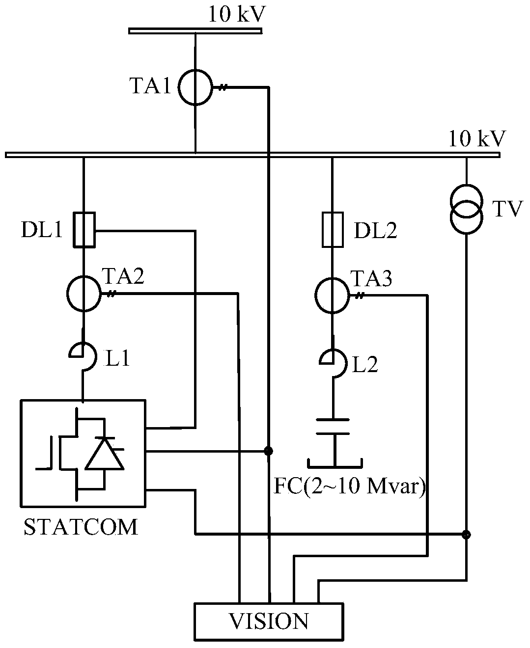
[0024] A method for testing response time of a dynamic reactive power compensation device, including a load compensation response time testing step, a step response time testing step, and a voltage transient drop response time testing step. The dynamic reactive power compensation device described in this embodiment is a STATCOM.

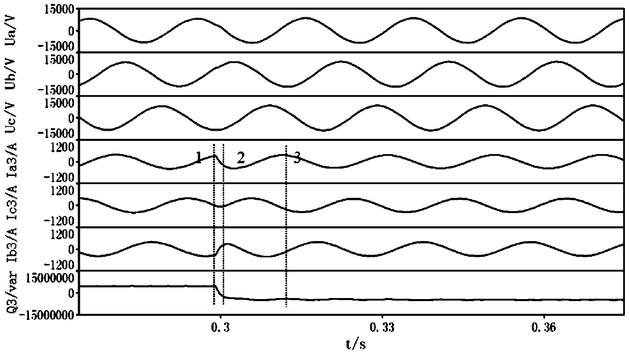
[0025] Load compensation response time test steps: such as figure 2 As shown, STATCOM runs in parallel with capacitor bank FC, STATCOM is set in the load compensation running state, and the capacitor bank FC is switched on or off, and the bus voltage TV and total voltage when the capacitor bank FC is switched on or off are tested and recorded by the high-precision data recorder VISION. The instantaneous waveforms of incoming line current TA1, capacitor bank branch current TA3, and STATCOM output current TA2 are calculated according to bus voltage TV, total incoming line current TA1, capacitor bank branch current TA3, and STATCOM output current TA2 wa...


PUM


Abstract

The invention discloses a dynamic reactive power compensation device response time test method. The method comprises a load compensation response time test step, a step response time test step and a voltage transient drop response time test step; instantaneous reactive power squiggles under all states are calculated by an instantaneous reactive power calculation formula of a three-phase device, then all time points on the squiggles are determined, and load compensation response time, step response time and voltage transient drop response time are calculated. The response time test method has the characteristics of simple calculation and accurate results, the step response time and stabilization time can be accurately tested, and the existing response time concept misunderstanding is avoided.

Description

technical field [0001] The invention relates to a response time testing method of a dynamic reactive power compensation device, which belongs to the technical field of power electronics. Background technique [0002] In recent years, dynamic var compensation devices have been widely used in wind power, metallurgy, coal, power transmission and distribution and other fields, including SVC (static var compensator) and SVG (static var generator), among which SVG is also called STATCOM (Static Synchronous Compensator). SVC is divided into TCR (Thyristor Controlled Reactor), TSC (Thyristor Switched Capacitor), MCR (Magnetic Control Reactor) and TCT (Thyristor Controlled Transformer) according to different technologies. Compared with the traditional shunt capacitor device, the outstanding advantages of the dynamic reactive power compensation device are continuously adjustable capacity and fast response speed. At present, the response speed of the static var compensator SVC is gen...

Claims


Application Information

Patent Timeline
Patent Type & Authority Applications(China)
IPC IPC(8): G06F19/00G01R31/00
Inventor 陈晓宇蔡重凯李电王敏
Owner STATE GRID CORP OF CHINA
Why Eureka
Try Eureka