LED yellow light source for manufacturing yellow light chamber with semiconductors and manufacturing process of LED yellow light source for manufacturing yellow light chamber with semiconductors

A yellow light chamber and semiconductor technology, applied in the direction of semiconductor devices, electrical components, circuits, etc., can solve the problems of impure light color, poor color rendering, low yellow light efficiency, etc., and achieve the effect of low light efficiency

Active Publication Date: 2014-09-17
JIANGMEN LT LIGHTING
View PDF4 Cites 4 Cited by
  • Summary
  • Abstract
  • Description
  • Claims
  • Application Information

AI Technical Summary

Problems solved by technology

Yellow lamps manufactured by this method often have defects such as low luminous efficiency, poor color rendering, serious light decay, and impure light color.

Method used


Image

  • LED yellow light source for manufacturing yellow light chamber with semiconductors and manufacturing process of LED yellow light source for manufacturing yellow light chamber with semiconductors
  • LED yellow light source for manufacturing yellow light chamber with semiconductors and manufacturing process of LED yellow light source for manufacturing yellow light chamber with semiconductors
  • LED yellow light source for manufacturing yellow light chamber with semiconductors and manufacturing process of LED yellow light source for manufacturing yellow light chamber with semiconductors

Examples


specific Embodiment 1

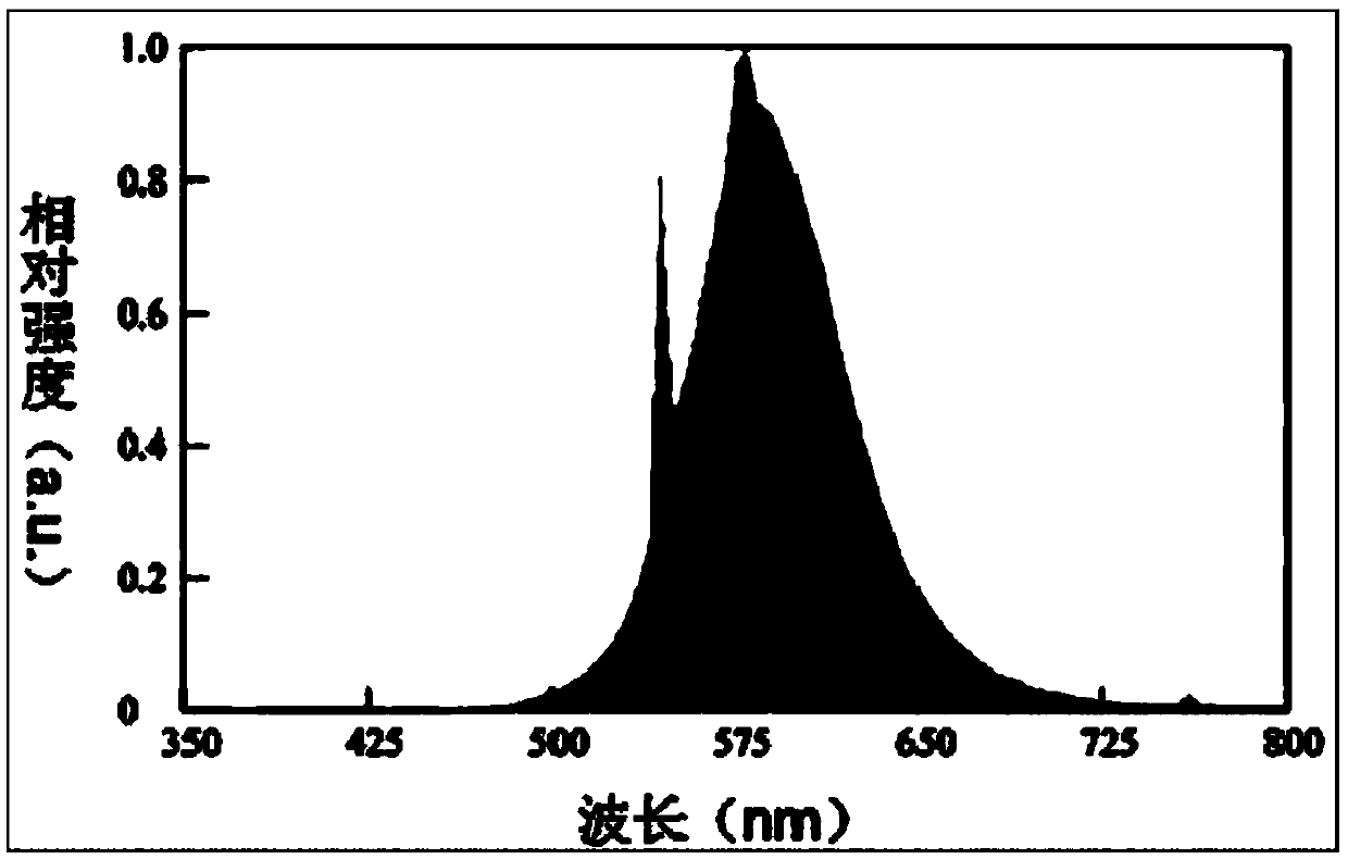
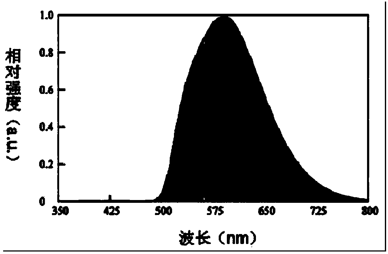
[0041] Specific example 1, the red phosphor uses BR, which accounts for 2%-9% of the yellow phosphor; the green phosphor uses TMG (silicate system), and the non-sulfide green fluorescent phosphor (GP) may also reach Good experimental results; the green fluorescent phosphor LuAG can also achieve the experimental results, and the dosage accounts for 9%-45% of the yellow phosphor dosage; the yellow phosphor uses YAG, and the LED chip uses blue chips. The ratio of glue A to glue B is 1:1. The spectrum test results of the obtained COB packaged light source are as follows: image 3 . In addition, the color rendering index of the packaged light source is 57.1, and the color temperature is 2899K. The spectral power distribution from the test image 3 and figure 1 It can be seen from the comparison that the spectrum of the packaged light source is smoother, and the coverage effect of blue light is very good, and the color rendering is better.

specific Embodiment 2

[0042] Specific embodiment 2, the red phosphor uses BR, accounting for 5% of the yellow phosphor; the green phosphor uses TMG, accounting for 34% of the yellow phosphor; the yellow phosphor uses YAG, and the LED chip uses blue chips. The ratio of glue A to glue B is 1:1. The spectrum test results of the obtained COB packaged light source are as follows: Figure 4. In addition, the color rendering index of the packaged light source is 51.5, and the color temperature is 2784K. The spectral power distribution from the test Figure 4 and figure 1 It can be seen from the comparison that the spectrum of the packaged light source is smoother, and the coverage effect of blue light is good, and the color rendering is better.

specific Embodiment 3

[0043] In specific embodiment 3, BR is used as the red phosphor, accounting for 4% of the yellow phosphor; TMG is used as the green phosphor, 30% of the yellow phosphor is used; YAG is used as the yellow phosphor, and blue chips are used as the LED chip. The ratio of glue A to glue B is 1:1. The spectrum test results of the obtained COB packaged light source are as follows: Figure 5 . In addition, the color rendering index of the packaged light source is 49.4, and the color temperature is about 2777K. The spectral power distribution from the test Figure 5 and figure 1 It can be seen from the comparison that the spectrum of the packaged light source is smoother, and the coverage effect of blue light is good, and the color rendering is better.

[0044] Below is the parameter contrast of specific embodiment 1,2,3 and traditional yellow light:

[0045]

[0046] Table 1 Concrete Embodiment 1, 2 compares with traditional yellow light parameter

[0047] From the comparison...


PUM

PropertyMeasurementUnit
Color temperatureaaaaaaaaaa

Abstract

The invention discloses an LED yellow light source for manufacturing a yellow light chamber with semiconductors and a manufacturing process of the LED yellow light source for manufacturing the yellow light chamber with the semiconductors. LED fluorescent glue for packaging the LED yellow light source is mainly composed of silica gel, green fluorescent powder, red fluorescent powder and yellow fluorescent powder in a mixed mode. According to weight, the green fluorescent powder, the red fluorescent powder and the yellow fluorescent powder are jointly 40%-70% of the total amount of the silica gel, wherein the weight proportion of the yellow fluorescent powder to the green fluorescent powder to the red fluorescent powder is 1:0.2-0.5:0.01-0.10, and the peak-emission wavelength of the green fluorescent powder ranges from 490 nm to 540 nm. As the LED fluorescent glue which is better than a traditional yellow lamp in lighting effect and color rendering index is adopted, when the LED yellow light source is used for manufacturing finished lamps, the traditional yellow lamp can be well replaced for manufacturing the yellow light chamber with the semiconductors, and the defects that the traditional yellow lamp is low in lighting effect, poor in reality, serious in light attenuation and the like.

Description

technical field [0001] The invention relates to an LED encapsulation light source and a manufacturing process thereof, in particular to an LED yellow encapsulation light source used in a semiconductor manufacturing yellow light chamber and a manufacturing process thereof. Background technique [0002] Due to the many advantages of LEDs such as energy saving, environmental protection, and easy adjustment of light and color, LEDs have developed rapidly in the field of lighting in recent years. More and more traditional lighting fixtures are replaced by LED lights, and good results have been achieved. [0003] In the field of semiconductor manufacturing, there is an etching technology - photolithography, which is widely used. In order to avoid the interference of other lights on the lithography exposure process, the exposure process is generally carried out in a relatively closed environment, and the light in the lithography room needs to remove short-wavelength light below 50...

Claims


Application Information

Patent Timeline
IPC IPC(8): H01L33/50
CPCH01L33/504H01L2933/0041
Inventor 黄承斌王忆彭渤李京生
Owner JIANGMEN LT LIGHTING
Why Eureka
Try Eureka