
Transformer Winding Fault Relay Protection Method Based on Winding Resistance Characteristics

A technology of transformer winding and winding resistance, applied in emergency protection circuit devices, electrical components, etc., can solve the problems of 10kV power distribution network power failure, impact, affecting the normal production of social industry and agriculture, to prevent the expansion of the fault range and accurate operation performance. reliable results

Active Publication Date: 2017-03-08
STATE GRID PUTIAN ELECTRIC POWER SUPPLY +3
View PDF6 Cites 0 Cited by
  • Summary
  • Abstract
  • Description
  • Claims
  • Application Information

AI Technical Summary

Problems solved by technology

Since the 220kV side of the 220kV three-phase three-winding transformer is connected to the 500kV power grid, the 110kV side of the 220kV three-phase three-winding transformer is connected to the 110kV power grid, and the 10kV side of the 220kV three-phase three-winding transformer is connected to the 10kV distribution network, when the current differential protection When a fault is detected in the three-phase three-winding transformer, all circuit breakers on the three sides of the three-phase three-winding transformer will be tripped. Caused unplanned blackout of 10kV distribution network, affecting the normal production of social industry and agriculture

Method used


Image

  • Transformer Winding Fault Relay Protection Method Based on Winding Resistance Characteristics
  • Transformer Winding Fault Relay Protection Method Based on Winding Resistance Characteristics
  • Transformer Winding Fault Relay Protection Method Based on Winding Resistance Characteristics

Examples


Embodiment Construction

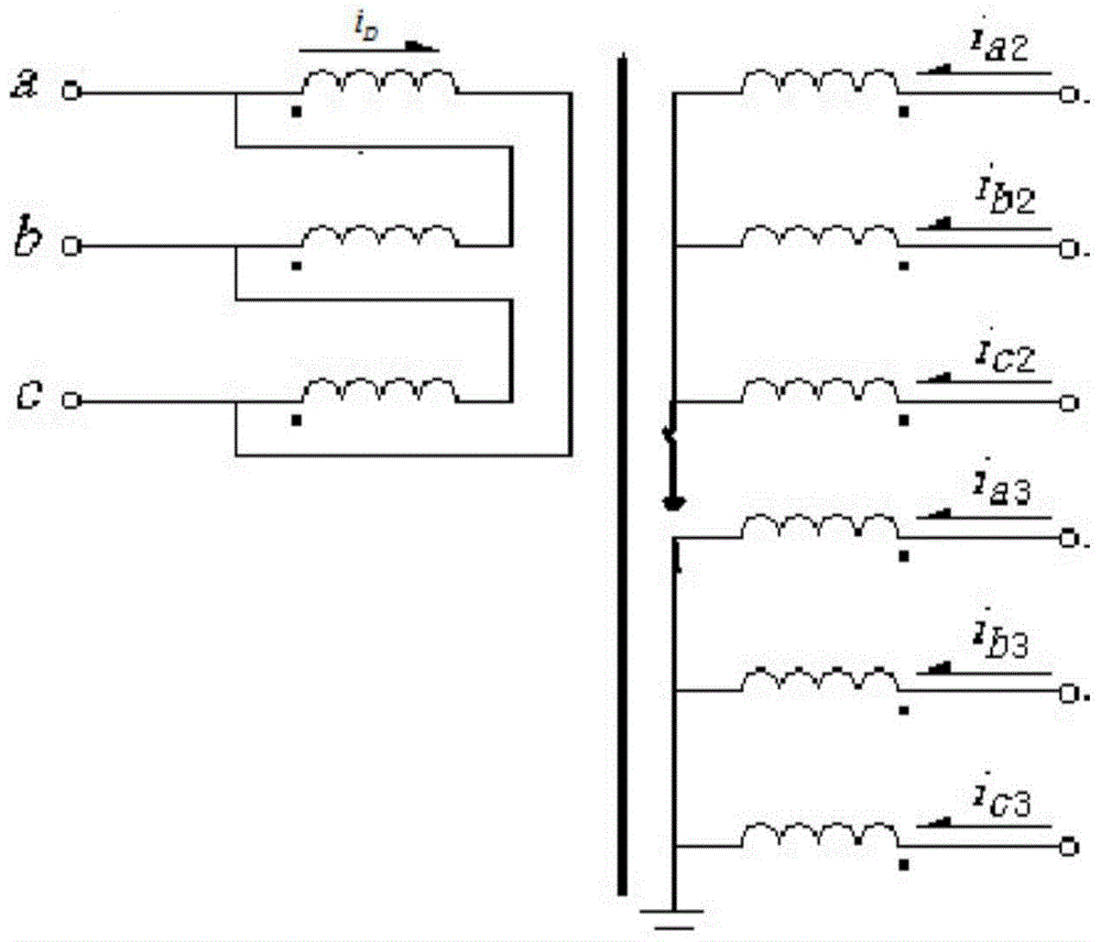
[0022] figure 1 A schematic diagram of a delta / Y / Y wiring transformer applying the method of the present invention. In this embodiment, the protection device measures the three-phase winding voltage u on the Y side of the two sets of transformers a2 , U b2 , U c2 And u a3 , U b3 , U c3 , Measure the three-phase winding current i on the Y side of the two sets of transformers a2 , I b2 , I c2 And i a3 , I b3 , I c3 , Measure the circulating current i on the △ side of the transformer D .

[0023] The protection device calculates the zero sequence voltage on the Y side of the two sets of transformers

[0024] The protection device calculates the zero sequence current on the Y side of the two sets of transformer

[0025] The protection device divides the zero sequence voltage u 02 , U 03 Zero sequence voltage converted to △ side according to transformation ratio Where n 1 Is the number of winding turns on the △ side of the transformer; n 2 , N 3 Is the number of turns of the two Y-si...


PUM


Abstract

The invention discloses a transformer winding fault relay protection method based on the winding resistance property. Zero-sequence voltages and zero-sequence currents on two sets of Y sides of a transformer are calculated respectively and are converted to be on the delta side of the transformer according to a corresponding conversion ratio respectively, parameters of two sets of Y-side windings of the transformer are converted to be on the delta side of the transformer according to the corresponding conversion ratio, a voltage vector of three sides of windings of the transformer is calculated, a current matrix of the transformer is calculated, then a resistance matrix of the three sides of windings of the transformer is calculated, and the resistance matrix and a setting threshold value form the transformer branch side winding fault relay protection criterion. The three-phase and three-winding transformation branch side winding fault relay protection is achieved by the utilization of the resistance properties of the three sides of windings of the transformer, action performance is not affected by field current, transition resistance and load current of the transformer and is accurate and reliable, a three-phase and three-winding transformation branch side winding fault tripping corresponding side breaker is achieved, and the fault range is effectively prevented from being enlarged.

Description

Technical field [0001] The invention relates to the technical field of power system relay protection, in particular to a transformer winding fault relay protection method based on winding resistance characteristics. Background technique [0002] 220kV transformers widely used in power systems usually use three-phase three-winding transformers. In order to ensure that the phase potential is close to the sine wave and provide a path for the third harmonic, the three-phase three-winding transformer must have a set of windings with delta connection, so the connection method is △ / Y / Y connection. [0003] The current differential protection is the main protection of the transformer. In order to make the current differential amount zero during normal operation, it is necessary to convert the two sets of Y-side currents of the transformer to the △-side or the △-side currents to the two sets of Y-sides to eliminate unbalance. Current. In order to eliminate the unbalanced current, the curr...

Claims


Application Information

Patent Timeline
Patent Type & Authority Patents(China)
IPC IPC(8): H02H7/04
Inventor 曾惠敏林富洪
Owner STATE GRID PUTIAN ELECTRIC POWER SUPPLY
Learn More