
Plasma torch having failure prediction function

A plasma and fault prediction technology, which is applied in the testing of plasma, measuring devices, machines/structural components, etc., can solve problems such as shortened life, delayed fault response, and inability to quickly respond to component faults, so as to prevent the expansion of the fault range Effect

Pending Publication Date: 2022-02-18
尤内深股份公司
View PDF0 Cites 0 Cited by
  • Summary
  • Abstract
  • Description
  • Claims
  • Application Information

AI Technical Summary

Problems solved by technology

[0005] In the prior art, there is the following problem: the corrosive gas containing F and Cl ions in the decomposed waste gas flows to the outlet side of the plasma torch through the eddy current, thereby damaging the anode electrode made of copper and shortening the service life
[0009] As a result, until the plasma torch fails, it cannot be identified, in other words, the failure of the plasma torch cannot be predicted or predicted, thereby inevitably delaying the response to the failure
[0010] In addition, due to the leakage of cooling water caused by the corrosion of the anode, secondary corrosion of other components including the manifold occurs. Therefore, not only cannot quick response to component failures, but also cannot quickly replace components, and there is even a possibility that the range of failures may expand. possibility

Method used


Image

  • Plasma torch having failure prediction function
  • Plasma torch having failure prediction function
  • Plasma torch having failure prediction function

Examples


Embodiment Construction

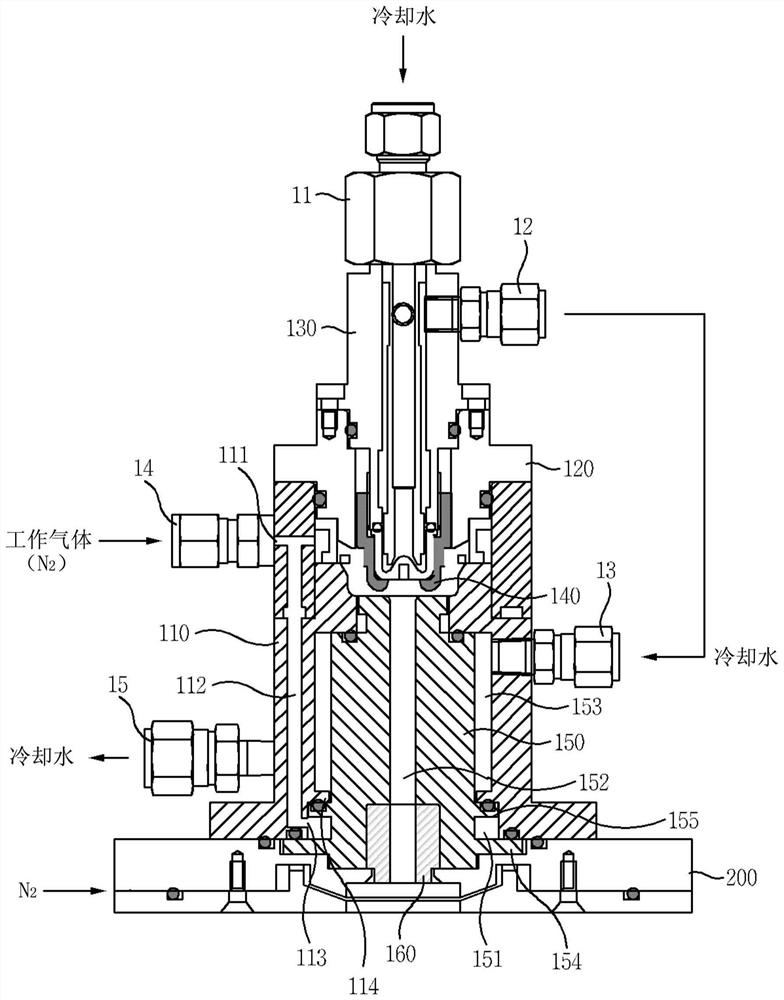
[0033] Hereinafter, the plasma torch will be described in detail centering on examples with reference to the drawings of the present invention.

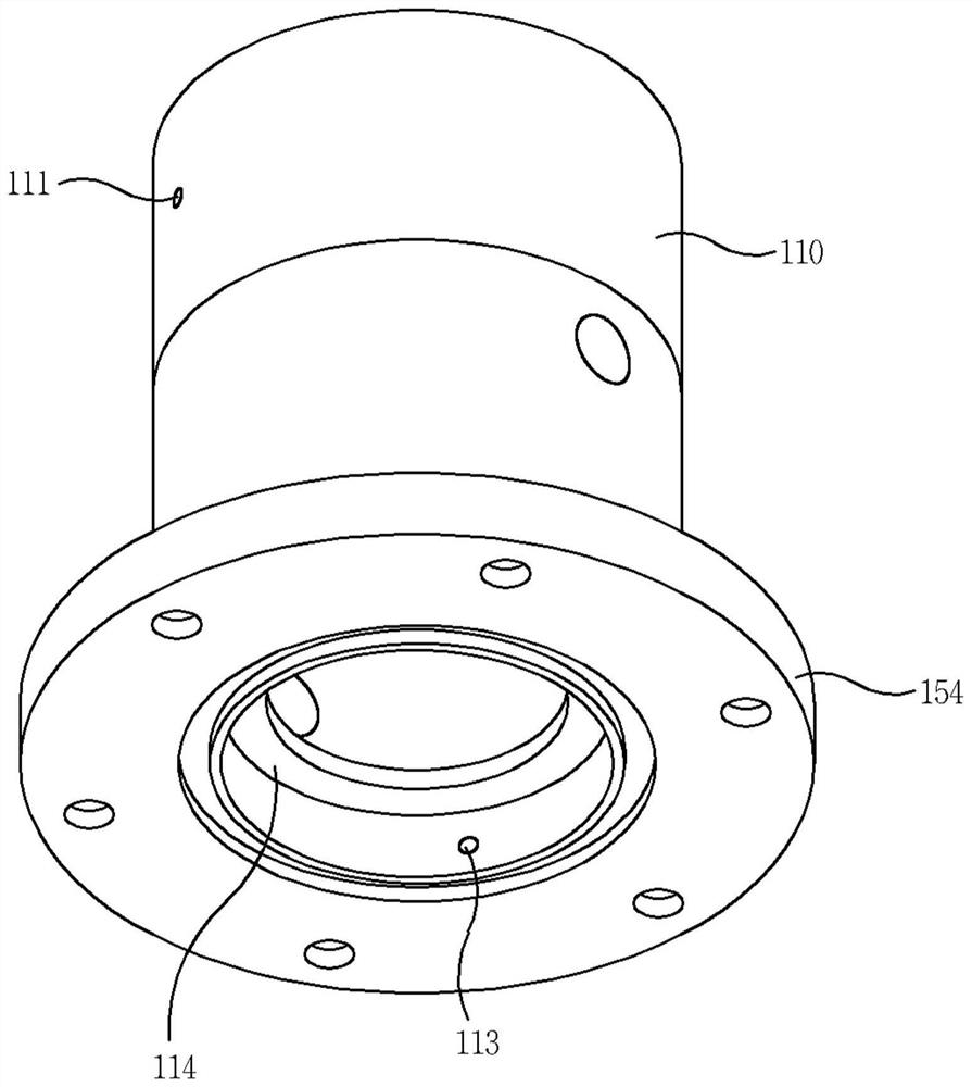
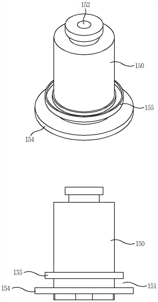
[0034] figure 1 represents a plasma torch according to an embodiment of the invention, figure 2 Indicates the body applied to the plasma torch, image 3 Indicates the anode applied to the plasma torch.

[0035] Since the arrangement of the body and cover, cathode and anode of a plasma torch is well known, it will be briefly described below.

[0036] Working gas (N 2 ) into the port 14, and the cooling water inflow port 13 and the outflow port 15 for cooling the anode 150 are respectively provided on opposite sides.

[0037] An insulating block 120 is interposed on the upper part of the main body 110 and a cover 130 is combined. An inflow port 11 and an outflow port 12 for inflow and outflow of cooling water for cooling the cathode 140 are respectively provided on the top and sides of the cover 130 .

[0038] Here, the cooling w...


PUM


Abstract

Disclosed is a plasma torch having a failure prediction function. A guide channel is formed inside a wall of a main body so as to communicate with an injection hole for supplying a working gas, and a discharge hole exposed to the inside of the main body is formed at the end of the guide channel so that a discharge hole communicates with an accommodation space. When an anode is corroded to form a hole, the working gas filled in the accommodation space leaks through the hole, so that the accommodation space maintains a sealed state in which the working gas is filled in the accommodation space.

Description

technical field [0001] The present invention relates to a plasma spray gun, in particular to a technology capable of preventing the expansion of corrosion caused by cooling water leakage. Background technique [0002] A spray gun that applies high temperature to a specific portion for the purpose of welding, cutting, surface treatment, waste burning, etc. is provided in various structures depending on the form of fuel to be burned. [0003] Recently, it is widely popularized and can achieve higher burning hot plasma torch. [0004] In particular, in the semiconductor manufacturing process, a high temperature of 10,000° C. or higher is required to treat and discharge harmful waste gases such as fluorine compounds including perfluorinated compound (PFC: PerFluoro Compound) gas in an environmentally friendly manner. [0005] In the prior art, there is a problem that the corrosive gas containing F and Cl ions in the decomposed exhaust gas flows toward the outlet side of the pl...

Claims


Application Information

Patent Timeline
IPC IPC(8): G01M99/00G01M3/02H05H1/26
CPCG01M99/005G01M3/02H05H1/26H05H1/34H05H1/28H05H1/3473
Inventor 尹泰爽郑义淳南德祐
Owner 尤内深股份公司
Learn More