Receiver circuit, semiconductor integrated circuit, and test method

A receiver and circuit technology, used in digital circuit testing, electronic circuit testing, receiver monitoring, etc., can solve the problems of impedance mismatch measurement error and accuracy degradation of transmission lines.

Active Publication Date: 2014-09-17
SOCIONEXT INC
View PDF5 Cites 6 Cited by
  • Summary
  • Abstract
  • Description
  • Claims
  • Application Information

AI Technical Summary

Problems solved by technology

However, in this case, the accuracy of the test deteriorates due to loss, impedance mismatc

Method used


Image

  • Receiver circuit, semiconductor integrated circuit, and test method
  • Receiver circuit, semiconductor integrated circuit, and test method
  • Receiver circuit, semiconductor integrated circuit, and test method

Examples


Embodiment Construction

[0029] Embodiments will now be described with reference to the drawings, wherein like reference numerals refer to like elements throughout.

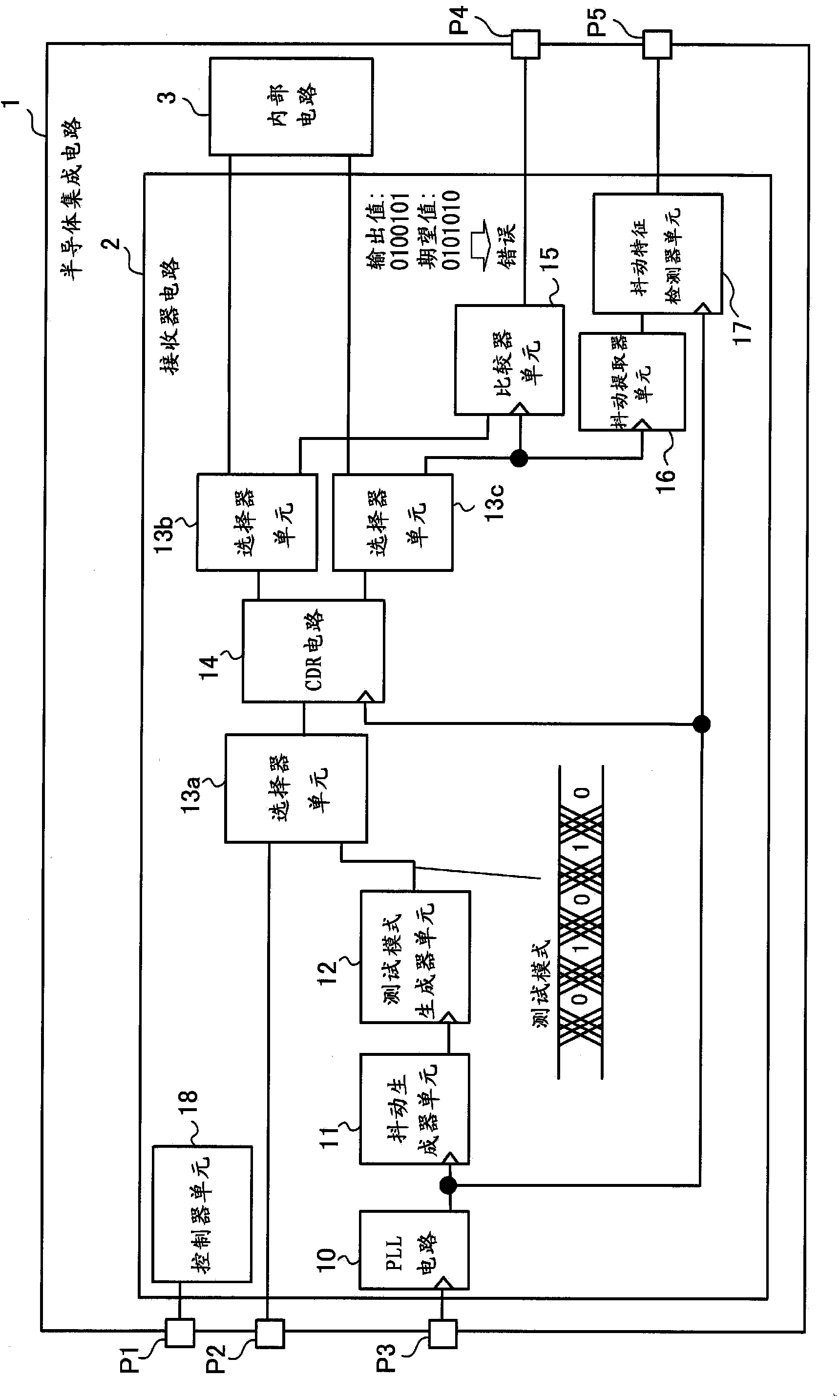
[0030] figure 1 is an example of the semiconductor integrated circuit according to the embodiment.

[0031] The semiconductor integrated circuit 1 includes: a receiver circuit 2; an internal circuit 3 that performs determination operations based on data and clocks received by the receiver circuit 2; and terminals P1, P2, P3, P4, and P5 that input and output various signals.

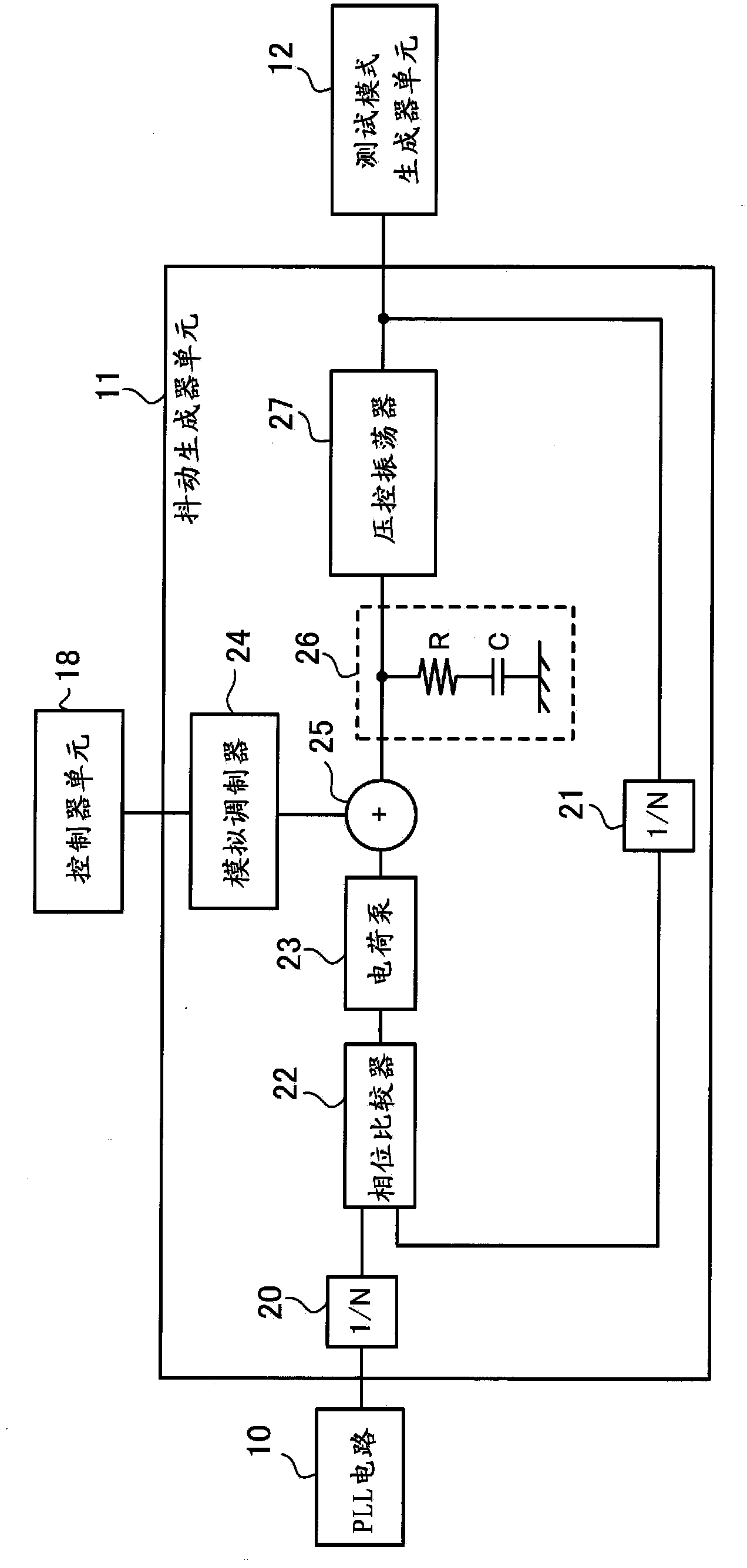
[0032] The receiver circuit 2 includes: a phase locked loop (Phase Locked Loop, PLL) circuit 10, a jitter generator unit 11, a test pattern generator unit 12, selector units 13a, 13b and 13c, a CDR circuit 14, a comparator unit 15, A jitter extractor unit 16 , a jitter signature detector unit 17 , and a controller unit 18 . Each of the jitter generator unit 11, the test pattern generator unit 12, the selector units 13a, 13b, and 13c, the comparator unit 15, the ji...


PUM


Abstract

The invention relates to a receiver circuit, a semiconductor integrated circuit, and a test method. A receiver circuit includes a CDR circuit, a jitter generator unit, a test pattern generator unit, and a comparator unit. The jitter generator unit generates jitter having first characteristics (frequency and amplitude). The test pattern generator unit generates a test pattern to which the jitter is added, and supplies the test pattern to the CDR circuit. The comparator unit compares a value outputted from the CDR circuit with an expected value and outputs a comparison result.

Description

technical field [0001] Embodiments discussed herein relate to receiver circuits, semiconductor integrated circuits, and testing methods. Background technique [0002] Clock and Data Recovery (CDR, Clock and Data Recovery) for recovering data and clocks from received signals is employed in high-speed interfaces and the like included in semiconductor devices. [0003] For example, the following two methods are used to test the receiver circuit with CDR function. [0004] One method is as follows: a tester provides a test pattern to a receiver circuit, and a BIST (Built-In Self Test) circuit included in the receiver circuit determines whether the test pattern is properly maintained. [0005] Another method is as follows: place the transmitter circuit that generates and transmits the test pattern in the same chip where the receiver circuit is placed or place the transmitter circuit outside the chip where the receiver circuit is placed (for example, on an evaluation board) . T...

Claims


Application Information

Patent Timeline
IPC IPC(8): H03K5/156H03K19/0175G01R31/30G01R31/317
CPCH04B17/29H04B17/008G01R31/31709H04L1/205
Inventor 小野寺充
Owner SOCIONEXT INC
Why Eureka
Try Eureka