Pneumatic manipulator material receiving device

A technology of a pneumatic manipulator and a feeding device, which is applied in metal processing and other directions, can solve problems such as affecting the quality of the workpiece, and achieve the effect of prolonging the service life.

Active Publication Date: 2014-09-24
宁波宫铁智能科技有限公司
View PDF7 Cites 3 Cited by
  • Summary
  • Abstract
  • Description
  • Claims
  • Application Information

AI Technical Summary

Problems solved by technology

[0003] At present, pneumatic manipulators are also widely used on lathes and machine tools in various automated production lines. In practical applications, these lathes or machine tools are often equipped with feeding devices for feeding and receiving devices for unloading. , The feeding device, the material receiving device and the pneumatic manipulator cooperate to make the automatic production line more convenient and fast. For example, the utility model patent of CN201172171Y discloses a kind of automatic pipe cutting machine material receiving device, including the bracket installed on the pipe cutting machine body, The bracket is provided with a feeding chute with openings at both ends, and a feeding tray is arranged on the feeding trough, and the feeding tray can slide on the feeding trough, and a cylinder is fixedly installed on the feeding trough, and the piston of the cylinder is fixedly connected with the feeding tray. The material receiving device can meet the dual requirements of material receiving and unloading, and can directly transfer the workpiece to the storage box, which improves the processing efficiency of the pipe cutting machine, but at the same time has the following shortcomings: 1. When unloading, the material receiving tray is The feeding trough moves toward its rear end, and a large inertia will be generated during the movement. When the receiving tray moves to the predetermined position and stops, the workpiece on the receiving tray will fall to the bottom with a force greater than itself under the inertia. In the storage box, the falling workpiece and the workpiece in the storage box will have a large impact, causing the two workpieces to be hard hit and damaged at the same time, which greatly affects the quality of the workpiece; 2. This material receiving device passes through the receiving tray The feeding function is realized by moving on the feeding trough. The receiving tray is open. After the workpiece is processed, it will directly fall into the receiving tray and automatically slide into a fixed position. Generally, the workpiece is higher than the receiving tray. When the workpiece falls into the receiving tray When the material is on the tray, the workpiece and the receiving tray are hard-impacted, which not only easily damages the processed workpiece, affects the quality of the workpiece, but also causes the deformation of the receiving tray, and the deformation of the receiving tray will make the bottom of the receiving tray and the feeding chute Friction causes the material receiving tray to move inflexibly on the feeding trough, which greatly affects the use of the material receiving device; 3. The workpiece falls from the processing end into the material trough, and under the impact, some workpieces will rebound on the material trough And it falls out of the material chute, and picking up the workpiece adds unnecessary troubles, so there are obvious defects in the function of material receiving and unloading of the material receiving tray, and its functions of material receiving and unloading are greatly reduced

Method used


Image

  • Pneumatic manipulator material receiving device
  • Pneumatic manipulator material receiving device
  • Pneumatic manipulator material receiving device

Examples


Embodiment Construction

[0025] The following are specific embodiments of the present invention and in conjunction with the accompanying drawings, the technical solutions of the present invention are further described, but the present invention is not limited to these embodiments.

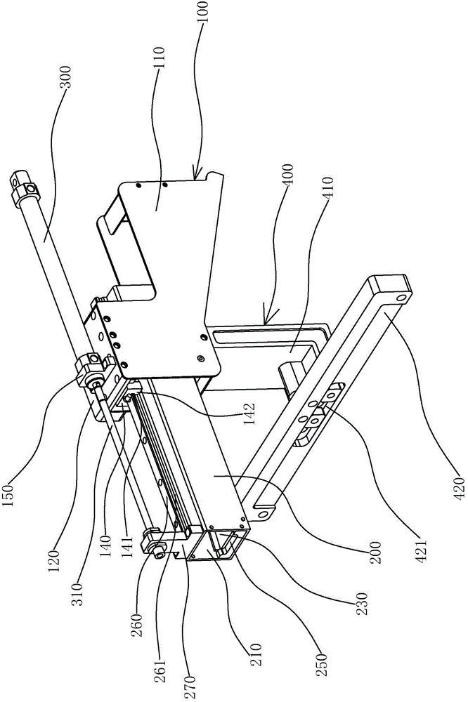
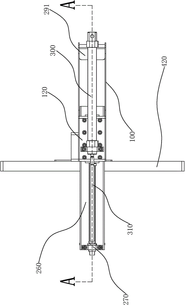
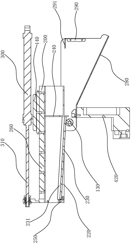
[0026] Such as figure 1 As shown, a pneumatic manipulator material receiving device of the present invention is installed on a frame, and includes a material cover frame 100 through front and rear and a material tube 200 arranged in the material cover frame 100. The material cover frame 100 includes symmetrically arranged parallel The two cover plates 110 and the mounting plates 120 fixedly connected to the tops of the two cover plates 110 respectively, such as image 3 , Figure 5 As shown, a roller 130 is installed horizontally and horizontally between two cover plates 110. The material tube 200 is a square tubular shape arranged horizontally in the axial direction and has a feed port 210 at the front end of the materia...


PUM


Abstract

The invention provides a pneumatic manipulator material receiving device and belongs to the technical field of automatic lathes; the technical problems that workpieces are easy to damage during the material receiving process of a traditional material receiving device, and the material receiving performance of the traditional material receiving device is poorer are solved by the pneumatic manipulator material receiving device provided by the invention. The pneumatic manipulator material receiving device is arranged on a rack, and comprises a feed cover frame and a feed pipe, wherein the front part and the rear part of the feed cover frame are through; the feed pipe is arranged in the feed cover frame and can move in the feed cover frame; the top part of the feed pipe is connected with the feed cover frame; a notch is formed in the bottom part of the feed pipe, and a material receiving plate of which one end is hinged to the feed pipe is arranged in the notch, wherein the material receiving plate and the feed pipe can be opened and closed; a rolling shaft is arranged in the feed cover frame, and the material receiving plate is put on the rolling shaft; when the feed pipe moves on the feed cover frame, the material receiving plate moves on the rolling shaft, and the material receiving plate and the feed pipe are opened or closed. The pneumatic manipulator material receiving device provided by the invention has the beneficial effects during the falling process of the workpieces, the inertia of the workpieces is smaller, so that the impact between the workpieces is reduced; the friction between the workpieces and the material receiving plate is smaller, so that abrasion to the material receiving plate and the workpieces is smaller, and the service life of the material receiving plate is prolonged.

Description

technical field [0001] The invention belongs to the technical field of automatic lathes, and relates to a material receiving device, in particular to a pneumatic manipulator material receiving device. Background technique [0002] Pneumatic manipulator is an automatic operation device that can imitate certain actions and functions of human hands and arms to grab, carry objects or operate tools according to a fixed program. It can replace human heavy labor to realize mechanization and automation of production, and reduce human labor. Labor intensity, save production cost, it can operate in harmful environment to protect personal safety, at the same time, pneumatic manipulator as a kind of manipulator, it has simple structure, light weight, fast action, stable, reliable, energy saving and no pollution to the environment, etc. Advantages, and thus widely used in various industries. [0003] At present, pneumatic manipulators are also widely used on lathes and machine tools in ...

Claims


Application Information

Patent Timeline
Patent Type & Authority Applications(China)
IPC IPC(8): B23B15/00
CPCB23Q7/00
Inventor 杨云林
Owner 宁波宫铁智能科技有限公司
Why Eureka
Try Eureka