
3D printing fill path generation method based on optimization of scanning line dip angle

A 3D printing and path generation technology, which is applied in the field of 3D printing filling path generation based on scanning line inclination optimization, can solve the problem of not considering the influence of scanning line inclination on processing efficiency and printing accuracy, and it is difficult for 3D printing technology to meet high efficiency and high precision. Requirements, restrictions on the improvement of 3D printing technology efficiency and precision, etc., to achieve the effect of improving processing efficiency and printing accuracy, good versatility, and improving processing efficiency

Active Publication Date: 2014-09-24
ZHEJIANG UNIV
View PDF4 Cites 34 Cited by
  • Summary
  • Abstract
  • Description
  • Claims
  • Application Information

AI Technical Summary

Problems solved by technology

[0004] However, the current parallel reciprocating linear path generation process does not consider the influence of the scan line inclination on processing efficiency and printing accuracy, thus ignoring the optimization of the scan line inclination, which limits the efficiency and accuracy of 3D printing technology to a certain extent. promote
This will make it difficult for 3D printing technology to meet the requirements of high efficiency and high precision in various fields.

Method used


Image

  • 3D printing fill path generation method based on optimization of scanning line dip angle
  • 3D printing fill path generation method based on optimization of scanning line dip angle
  • 3D printing fill path generation method based on optimization of scanning line dip angle

Examples


Embodiment Construction

[0042]The present invention will be further described below in conjunction with the accompanying drawings and specific embodiments.

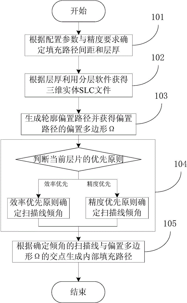
[0043] Such as figure 1 As shown, it is a flow chart of the 3D printing filling path generation method based on the scan line inclination optimization of the present invention, and the specific implementation steps are as follows:

[0044] Step 101, use 3D software to obtain the 3D model file of the 3D entity to be printed, determine that the filling path spacing is 0.15 mm according to the 3D printer used and the accuracy requirements to be achieved, and the layer thickness of the slice is 0.2 mm; in this step, each The structural configuration of each 3D printing device and the molding parameters of the printing materials used are different, and the allowed filling path spacing and layer thickness range are also different. At the same time, the higher the accuracy requirement, the smaller the path spacing and the thinner the layer thickness. ...


PUM


Abstract

The invention discloses a 3D printing technology fill path generation method based on optimization of a scanning line dip angle. The generation method comprises the following steps: determining a fill path interval, layer thickness, and an SLC (Single Level Cell) file of a to-be-processed entity; with the fill path interval as an offset distance, performing offset to obtain an offset polygon Omega; according to processing efficiency and printing precision requirements, judging the priority principle adopted by a current printing layer; if the priority principle refers to efficiency priority, determining the scanning line dip angle in an efficiency priority way, and if the priority principle refers to precision priority, determining the scanning line dip angle in a precision priority way; and finally, generating an internal fill path according to a point at which a scanning line with the determined dip angle is crossed with the offset polygon Omega. According to the provided 3D printing internal fill path generation method based on the optimization of the scanning line dip angle, the scanning line dip angle in generation of parallel reciprocating fill paths is optimized, the processing efficiency and the printing precision are further promoted, and the method is simple and effective, and good in universality.

Description

technical field [0001] The invention relates to the field of 3D printing technology path generation methods, in particular to a 3D printing filling path generation method based on scanning line inclination optimization. Background technique [0002] 3D printing technology first uses computer-aided design software to construct or obtain a three-dimensional solid model through reverse engineering, and then generates a layer-by-layer section of the three-dimensional model through layered software, and obtains a three-dimensional solid by layer-by-layer processing. Since the printing process uses liquid, powder or flake materials to realize the layer-by-layer processing of the section, any shape of the object can be processed by this technology. Therefore, in some fields that cannot be completed by traditional processing technology, 3D printing technology has developed rapidly, such as construction, aerospace, machinery, biomedicine and other fields have been widely used. Altho...

Claims


Application Information

Patent Timeline
IPC IPC(8): B29C67/00
Inventor 贺永金育安傅建中林志伟沈洪垚
Owner ZHEJIANG UNIV
Learn More