Spinning Point Of Spinning Machine And Method For Operation Of Same

A spinning machine, station technology, applied in spinning machine, open end spinning machine, continuous winding spinning machine, etc., can solve the problem of limiting spinning process, affecting the productivity of air-jet spinning machine, errors, etc. question

Active Publication Date: 2014-09-24
MASCHINENFABRIK RIETER AG
View PDF12 Cites 12 Cited by
  • Summary
  • Abstract
  • Description
  • Claims
  • Application Information

AI Technical Summary

Problems solved by technology

Furthermore, it is often necessary to remove certain sections of the yarn before spinning again, since this yarn end is largely unsuitable for the spinning process or contains yarn errors detected by the yarn monitor
[0005] Since the service robot must first drive to the respective spinning station before the spinning process, and only one spinning station can always be picked up by the robot, this necessary spinning process significantly limits the spinning process
This wiring process can significantly affect the productivity of the air-jet spinning machine, especially after several clear-cutting processes in the air-jet spinning machine

Method used


Image

  • Spinning Point Of Spinning Machine And Method For Operation Of Same
  • Spinning Point Of Spinning Machine And Method For Operation Of Same
  • Spinning Point Of Spinning Machine And Method For Operation Of Same

Examples


Embodiment Construction

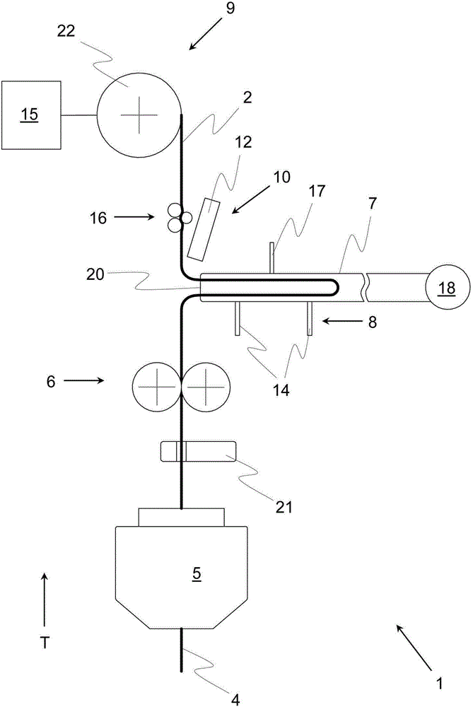
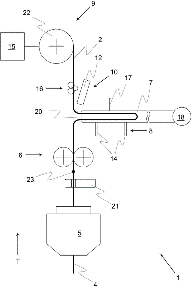
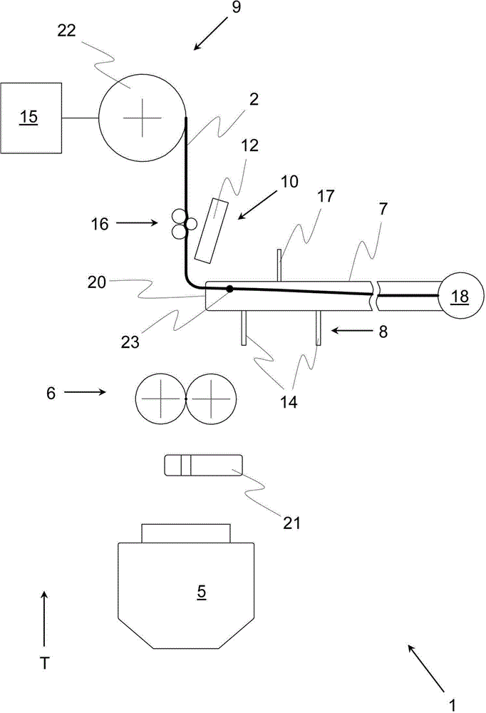
[0038] figure 1 The schematic diagram shows a spinning station 1 of a spinning machine according to the invention, which can be configured, for example, as an air-jet spinning machine or an open-end spinning machine, during the spinning process, during which the yarn 2 is made of composite fibers 4. The composite fibers 4 are generally conveyed here by means of a stretching mechanism (air-jet spinning machine) or a loosening unit (air-jet spinning machine) to a spinning unit 5 (in an air-jet spinning machine) correspondingly known from the prior art in an air swirl chamber, or in an open-end spinning machine, a rotor chamber), and rotates in the spinning unit 5 . In the figures, only the spinning station 1 is shown, but the corresponding spinning machine can of course also comprise a plurality of spinning stations 1 arranged one after the other, for example perpendicular to the drawing, and preferably of similar construction.

[0039] In addition, the shown spinning station...


PUM


Abstract

The invention relates to a spinning point (1) of a spinning machine, whereas the spinning point (1) includes a spinning unit (5), a drawing-off device (6) for the yarn (2) downstream of the spinning unit (5) in the direction of transport (T) and a yarn accumulator (7) downstream of the drawing-off device (6) for the intermediate accumulation of a section of yarn, whereas the yarn accumulator (7) is allocated a sensor system (8) for monitoring the filling level of the yarn accumulator (7), whereas the spinning point includes a spooling device (9) for the yarn (2) downstream of the yarn accumulator (7), along with a return unit (10), with the assistance of which an end of the yarn (11), which is found within the yarn accumulator (7) after a yarn break, is able to be returned in the area of the spinning point (1). What is also proposed is a method for the operation of a spinning point (1), characterized in that its spooling device (9) is stopped in such a manner that, after the stop of the spooling device (9), an end section of the yarn (2) remains within the yarn accumulator (7), that, subsequent to this, a part of the yarn (2) is separated with the assistance of a yarn separation unit (17) internal to the spinning point, and that the end of the yarn (11) that newly arises in this manner is returned with the assistance of a return unit (10) internal to the spinning point in the area of the spinning point (1), and that a spinning process is then carried out.

Description

technical field [0001] The invention relates to a spinning station of a spinning machine for producing yarn from composite fibers transported to the spinning station in the conveying direction. Furthermore, a method of operating a spinning station is proposed, in which, during spinning, the yarn produced in the spinning station is drawn out of the spinning station by means of a draw-off device, the drawn-out yarn being monitored by means of the yarn A device to monitor at least one physical parameter, the withdrawn yarn passes through a yarn store, the filling state of the yarn store is monitored by means of a sensor device, the yarn is wound by means of a winding device after passing through the yarn store, and according to the yarn store The filling state adjusts the winding speed of the winding device. Background technique [0002] The following description generally refers to a spinning machine suitable for making yarn from composite fibers placed in front of it. Air-j...

Claims


Application Information

Patent Timeline
Patent Type & Authority Applications(China)
IPC IPC(8): D01H4/02D01H4/50
CPCD01H4/02D01H4/50D01H15/00D01H4/48D01H1/115B65H51/205B65H67/081B65H2701/31D01H15/002
Inventor G·斯塔莱克M·库布勒G·沙夫勒E·皮拉J-O·里考特-鲁比奥
Owner MASCHINENFABRIK RIETER AG
Why Eureka
Try Eureka