Method For Detecting Changes Of Position Of Shaftless Spinning Rotor And Spinning Unit

一种纺纱单元、转杯的技术,应用在纺纱机、轴和轴承、测量装置等方向,能够解决不能获得附加空间、昂贵等问题

Inactive Publication Date: 2014-09-24
RIETER CZ AS
View PDF5 Cites 8 Cited by
  • Summary
  • Abstract
  • Description
  • Claims
  • Application Information

AI Technical Summary

Problems solved by technology

However, this solution is expensive and requires additional space for a second parallel system of sensors, detectors and evaluation circuits
Furthermore, due to the short length of the shaftless spinning rotor and due to the overall relatively small size of the spinning units in open-end spinning machines with active magnetic bearings, the shaftless spinning rotor length and spinning outside dimensions of the yarn unit, the necessary additional space cannot be obtained

Method used


Image

  • Method For Detecting Changes Of Position Of Shaftless Spinning Rotor And Spinning Unit
  • Method For Detecting Changes Of Position Of Shaftless Spinning Rotor And Spinning Unit
  • Method For Detecting Changes Of Position Of Shaftless Spinning Rotor And Spinning Unit

Examples


Embodiment Construction

[0013] From the following description of an example of an embodiment of an active magnetic bearing with a shaftless spinning rotor for a spinning unit of an open-end spinning machine, the present invention will become clearer.

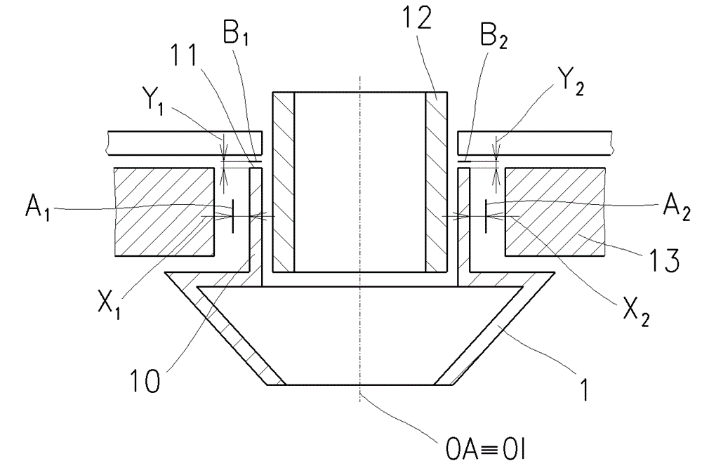
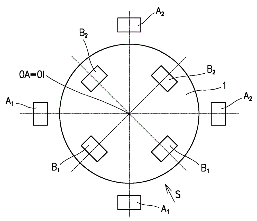
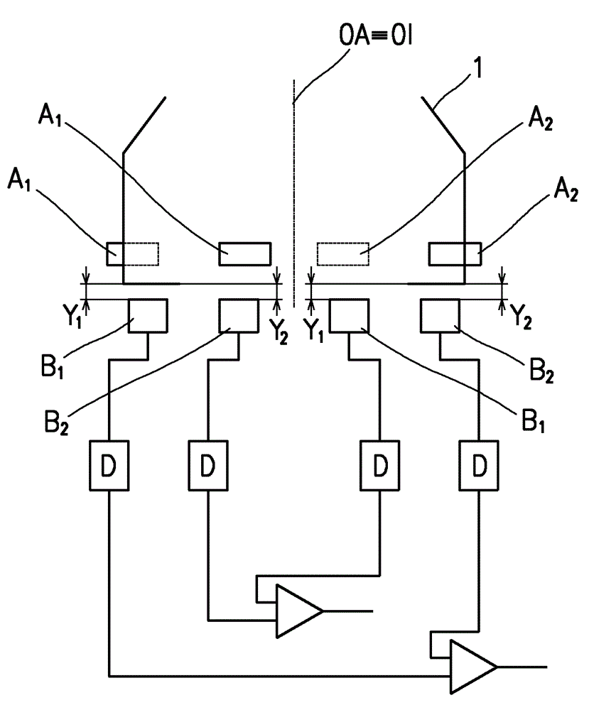
[0014] The open-end spinning machine includes at least one row of operating units positioned adjacent to each other. In addition to a number of other components, each operating unit also includes a spinning unit arranged with an active magnetic bearing, and the shaftless spinning rotor 1 is rotatably installed in the active magnetic bearing. The active magnetic bearing ensures that the position of the spinning rotor 1 relative to the other components of the spinning unit is maintained by the controlled magnetic stabilization system 13. The driving of the spinning rotor 1 is ensured by a controlled electromagnetic driving system 12.

[0015] Below the position of the spinning rotor 1, we understand that the spinning rotor 1 is positioned in a three-dimensio...


PUM


Abstract

The invention relates to a method for detecting changes of position of a shaftless spinning rotor of an open-end spinning machine in a cavity of an active magnetic bearing and a spinning unit supporting the open-end spinning machine of a driving magnetic bearing of the shaftless spinning rotor. Continuously is detected radial shifting of the spinning rotor and simultaneously is continuously detected inclination of the spinning rotor, whereupon according to the detected changes in the position of the spinning rotor is determined shifting and / or inclination of the spinning rotor which is used for subsequent adjustment of the controlling of position of the spinning rotor in the active magnetic bearing. Position sensors of the spinning rotor are grouped in pairs whereby two sensor pairs for determining radial shift of the spinning rotor are arranged on opposite sides of the spinning rotor counter the spinning rotor cylindrical wall; At the same time, the two sensor pairs for determining incline of the spinning rotor are arranged on opposite sides of the spinning rotor counter the spinning rotor wall, which is perpendicular to the spinning rotor axis of rotation.

Description

Technical field [0001] The present invention relates to a method for detecting the position change of a shaftless spinning rotor of an open-end spinning machine in a cavity of an active magnetic bearing, wherein the position of the spinning rotor is detected by a sensor system and based on the detected The position of the spinning rotor is changed to adjust the control of the active magnetic bearing, so as to eliminate the undesired changes in the position of the spinning rotor in the cavity of the active magnetic bearing. [0002] The present invention also relates to a spinning unit of a free-end spinning machine having an active magnetic bearing for supporting a shaftless spinning rotor, which includes a component for generating and controlling a magnetic field in which the spinning rotor is arranged, wherein The bearing also includes a sensor for the position of the spinning rotor, the sensor is connected to a detector of its output signal, and is connected to an evaluation ci...

Claims


Application Information

Patent Timeline
Patent Type & Authority Applications(China)
IPC IPC(8): D01H13/32
CPCF16C32/0446F16C32/0451D01H4/44D01H4/12F16C2340/18G01B7/14
Inventor M.莫拉维M.斯图萨克J.斯劳彭斯基
Owner RIETER CZ AS
Why Eureka
Try Eureka