Building support for construction

A support plate and support rod technology, which is applied in the fields of architecture, building structure, and on-site preparation of building components, can solve problems such as construction safety affecting building quality, problems with building construction quality, and tilting of the top support surface, etc. Achieve the effect of low cost, long service life and stable structure

Active Publication Date: 2014-09-24
浙江升浙建设集团有限公司
View PDF5 Cites 7 Cited by
  • Summary
  • Abstract
  • Description
  • Claims
  • Application Information

AI Technical Summary

Problems solved by technology

The supporting force on the building is basically large, so the single support rod is easy to bend when used, the service life of the support is short, and once the top of the support is tilted, the lifted building will be unevenly stressed and easy to tilt or deviate, or the support If the support fails and damages the upper part of the building, it will seriously affect the quality of the building, and even cause the building to collapse and cause danger
At the same time, when the bracket is fine-tuned, the uneven force on the fine-tuning parts or excessive pressure may cause the bracket parts to be easily damaged, or the un

Method used


Image

  • Building support for construction
  • Building support for construction
  • Building support for construction

Examples


Embodiment 1

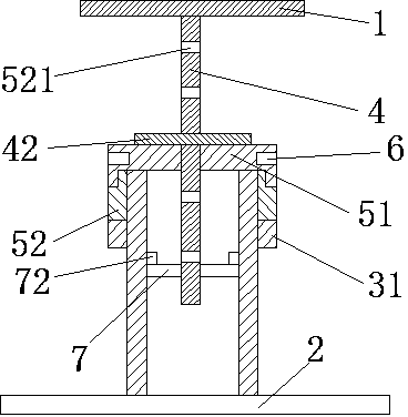
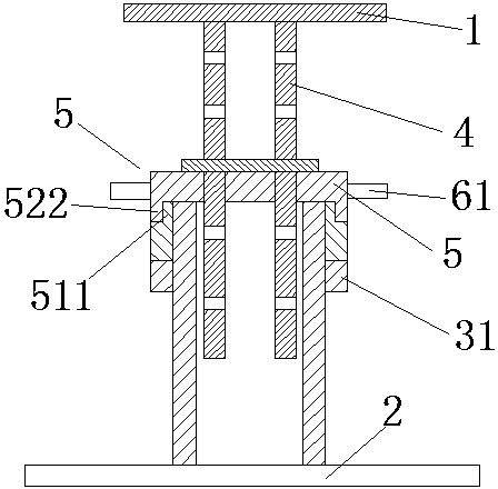
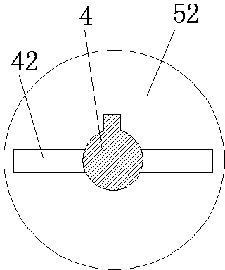
[0036] A building bracket for construction, comprising an upper support plate 1 and a lower support plate 2, a guide cylinder 3 is vertically arranged on the lower support plate 2, a support rod 4 is vertically arranged on the lower surface of the upper support plate 1, and a guide cylinder 3 is sleeved on the upper end A support sleeve 5 that can move up and down along the guide cylinder 3. The support sleeve 5 includes a cylinder body 51 sleeved on the guide cylinder 3 and a cylinder cover 52 that is buckled on the top of the cylinder body 51 and is adapted to the support rod 4. The support rod 4 passes through the through hole from top to bottom, and is inserted into the guide cylinder 3 described in the through hole 521. A limiting part is arranged between the cylinder body 51 and the cylinder cover 52 to prevent the cylinder cover from translating on the horizontal plane. The limiting component includes The inner protruding ring 511 on the top of the barrel body 51 and the...

Embodiment 2

[0040] The difference from the above implementation is that the bottom end of the barrel 51 is provided with an adjusting ring 31 having an internal thread adapted to the external thread.

Embodiment 3

[0042] The difference from the above implementation is that the through hole 521 is a square hole, and the support rod is a square rod, and there is no need to set a limit bar.


PUM


Abstract

The invention relates to the field of buildings, in particular to a building support for construction. The building support is high in supporting intensity and convenient to use. The building support comprises an upper supporting plate and a lower supporting plate. A guiding cylinder is arranged on the lower supporting plate. A supporting rod is arranged on the lower surface of the upper supporting plate. A supporting sleeve is arranged at the upper end of the guiding cylinder in a sleeved mode. The supporting sleeve comprises a sleeve body and a sleeve cover. The supporting rod penetrates through a through hole from top to bottom and is inserted into the guiding cylinder. A limiting part is arranged between the sleeve body and the sleeve cover. A position clamping part is arranged on the outer side of the sleeve cover. Outer threads are arranged on the outer cylinder wall of the guiding cylinder. Inner threads are arranged on the inner side of the lower portion of the sleeve body, or an adjusting ring is arranged at the bottom end of the sleeve body. A plurality of through grooves are formed in the supporting rod. The support further comprises locating inserting strips matched with through grooves. Parts of the building support are balanced in stress and stable in supporting and pushing, each operation action can be completed under a visible condition, visibility is achieved, the upper supporting plate and the supporting rod cannot rotate automatically, safety is high, supporting strength is high, and the angle of the upper supporting plate can be adjusted by adjusting the sleeve cover.

Description

technical field [0001] The invention relates to the construction field, in particular to a construction support with high support strength, long service life and convenient use. Background technique [0002] Most of the existing building supports are supported by a single support rod, and the fine-tuning parts are used for the final jacking. The overall structure is single and the supporting force is limited. The supporting force on the building is basically large, so the single support rod is easy to bend when used, the service life of the support is short, and once the top of the support is tilted, the lifted building will be unevenly stressed and easy to tilt or deviate, or the support If the support fails and damages the upper part of the building, it will seriously affect the quality of the building, and even cause the danger of the building collapsing. At the same time, when the bracket is fine-tuned, the uneven force on the fine-tuning parts or excessive pressure may...

Claims


Application Information

Patent Timeline
IPC IPC(8): E04G25/06
Inventor 陈晓
Owner 浙江升浙建设集团有限公司
Why Eureka
Try Eureka