Regeneration opportunity control method for DPF (Diesel Particulate Filter) of diesel engine

A particle trap and regeneration timing technology, which is applied in the direction of machines/engines, mechanical equipment, engine components, etc., can solve the problems of burning out carriers, local carbon load exceeding the standard, and uneven carbon adhesion

Active Publication Date: 2014-09-24
GREAT WALL MOTOR CO LTD
View PDF5 Cites 41 Cited by
  • Summary
  • Abstract
  • Description
  • Claims
  • Application Information

AI Technical Summary

Problems solved by technology

Another example is that after the engine is shut down in winter when the exhaust humidity is slightly high, the moisture accumulated inside the DPF may freeze together with the carbon particles. After the engine is restarted and runs for a period of time, part of the carbon may be taken away when the ice frozen inside the DPF is removed. , resulting in uneven carbon attachment inside the carrier, resulting in a short-term decrease in the estimated value of the carbon load
In the case of uneven carbon distribution inside the above-mentioned carrier, the carbon load estimation method based on pressure difference will cause wrong judgment of regeneration timing, resulting in local carbon load in the carrier exceeding the standard, and there is a risk of burning the carrier

Method used


Image

  • Regeneration opportunity control method for DPF (Diesel Particulate Filter) of diesel engine
  • Regeneration opportunity control method for DPF (Diesel Particulate Filter) of diesel engine
  • Regeneration opportunity control method for DPF (Diesel Particulate Filter) of diesel engine

Examples


Embodiment Construction

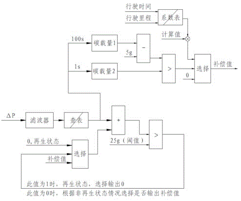
[0018] See figure 1 The present invention uses a differential pressure sensor to collect the differential pressure signal ΔP at both ends of the DPF, and obtains the DPF (Diesel Particulate Filter) carbon load corresponding to the filtered ΔP by referring to the correspondence table between the differential pressure value and the carbon load (soot) estimated value.

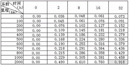
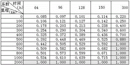
[0019] Table 1: Correspondence table of pressure difference and carbon loading

[0020] SOOT_INDEX SOOT_MASS 0.130 0.382.3 0.944.8 1.386.6 1.949.1 2.511.4 2.9413.4 3.4415.4 418.3 4.4421.6 5.0625.4 5.527.9 5.9430.2 6.5633.7 735.8 1260

[0021] In Table 1, SOOT_INDEX refers to the standard pressure drop coefficient produced only by carbon deposits, and SOOT_MASS refers to the weight of carbon deposits.

[0022] The estimated carbon load is divided into three ways, one is used for regular regeneration timing selection, the estimated carbon load is greater than the acceptable threshold (the maximum carbon load calculate...


PUM


Abstract

The invention relates to a regeneration time control method for a DPF (Diesel Particulate Filter) of a diesel engine. The method comprises the following steps: measuring a pressure difference value of both ends of the DPF in real time by utilizing a pressure difference sensor; obtaining an estimated value of a DPF carbon carrying quantity by looking up a table; simultaneously monitoring whether the estimated value of the DPF carbon carrying quantity has the suddenly-reduced phenomenon; when the estimated value of the DPF carbon carrying quantity has the suddenly-reduced phenomenon, calculating a compensation value of the DPF carbon carrying quantity according to a trip distance and trip time of a vehicle after last regeneration; then adding the estimated value of the DPF carbon carrying quantity and the compensation value of the DPF carbon carrying quantity to obtain a corrected value of the DPF carbon carrying quantity; and finally, according to the size of the corrected value of the DPF carbon carrying quantity, judging whether to trigger the DPF to enter a regenerated state. In the regeneration time control method for the DPF of the diesel engine, the compensation value of the DPF carbon carrying quantity is calculated according to the suddenly-reduced condition of the estimated value of the DPF carbon carrying quantity so as to correct the DPF carbon carrying quantity; the accuracy of estimated data of the DPF carbon carrying quantity when distribution of carbon particles inside a carrier is nonuniform is greatly improved, so that regeneration time is avoided being judged by mistake and safety of a carbon cigarette pellet carrier is ensured.

Description

Technical field [0001] The invention relates to a method for accurately grasping the regeneration timing of a diesel engine particle trap, and belongs to the technical field of engines. Background technique [0002] Diesel Particulate Filter (Diesel Particulate Filter) is a ceramic filter installed in the diesel engine exhaust system. It can capture soot particles before they enter the atmosphere to reduce particulate matter emissions. [0003] After the particulate trap captures the soot particles, it will cause the engine back pressure to increase, resulting in a decrease in engine performance. Therefore, combustion or other methods must be used to remove the soot particles. This process is called DPF regeneration. During the DPF regeneration process, the engine load suddenly decreases (such as suddenly returning to idle speed), the airflow in the DPF decreases sharply, and the heat dissipation speed is greatly reduced. While the oxygen content in the DPF increases, the combustio...

Claims


Application Information

Patent Timeline
Patent Type & Authority Applications(China)
IPC IPC(8): F01N9/00
CPCY02T10/40
Inventor 王宗勃王亮任向飞李颖涛
Owner GREAT WALL MOTOR CO LTD
Why Eureka
Try Eureka