
Fuel feed system oil sprayer and oil spray nozzle thereof

A technology of fuel supply system and fuel injector, which is applied in the direction of charging system, fuel injection device, machine/engine, etc. It can solve the problems of difficult processing, high cost, complex structure of fuel injector head, etc., and achieve simplified processing , improve the accuracy of parts, and simplify the electronic control

Inactive Publication Date: 2014-09-24
北京天纬燃油喷射技术股份有限公司
View PDF8 Cites 1 Cited by
  • Summary
  • Abstract
  • Description
  • Claims
  • Application Information

AI Technical Summary

Problems solved by technology

Seat surface throttling and nozzle throttling will make the nozzle head structure extremely complex and difficult to process
Technical methods such as double opening pressure need to change the structure of the injector and add additional devices, which increases the cost

Method used


Image

  • Fuel feed system oil sprayer and oil spray nozzle thereof
  • Fuel feed system oil sprayer and oil spray nozzle thereof
  • Fuel feed system oil sprayer and oil spray nozzle thereof

Examples


Embodiment 1

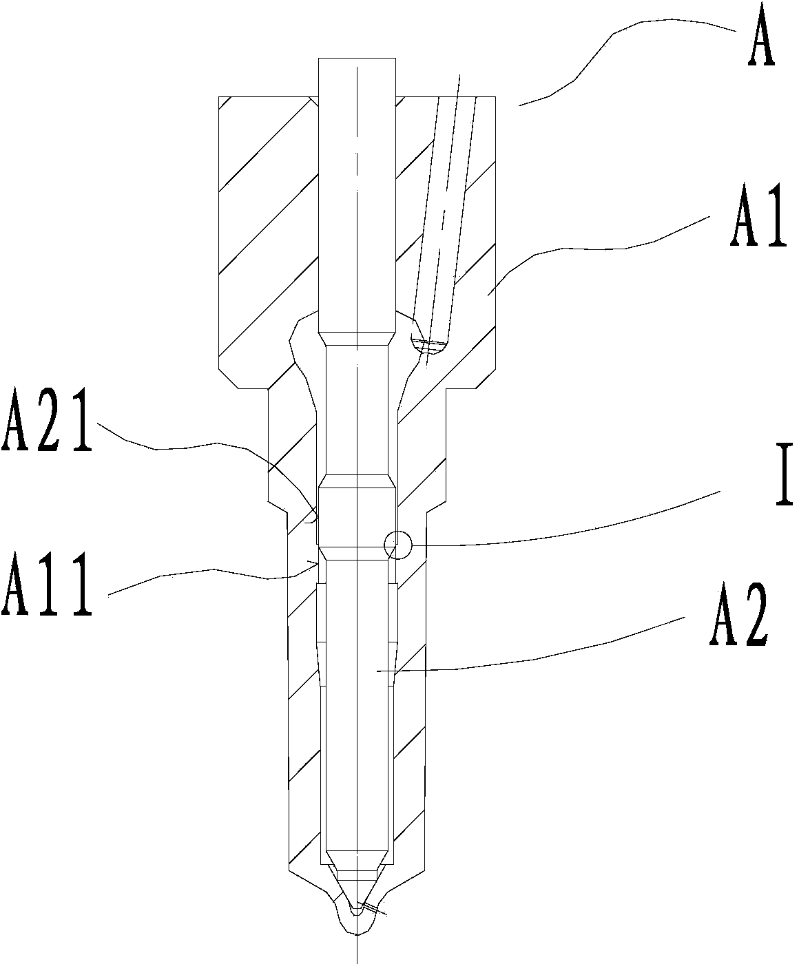
[0037] Such as Figure 2-5 As shown, the fuel injector A includes a needle valve body A1 and a needle valve A2, which are mated with each other. A first flange A11 is formed on the inner wall of the needle valve body A1, and the first flange A11 encloses an orifice, and the diameter of the orifice is consistent with the diameter of the coupling seal (coupling guide hole). A second flange A21 is configured on the outer wall of the needle valve A2; when the needle valve A2 is closed, a throttle ring C is formed between the vertical inner wall of the first flange A11 and the vertical outer wall of the second flange A21; When the needle valve A2 is fully opened, there is no matching section between the vertical inner wall of the first flange A11 and the vertical outer wall of the second flange A21 (that is, the throttle ring C disappears and does not work).

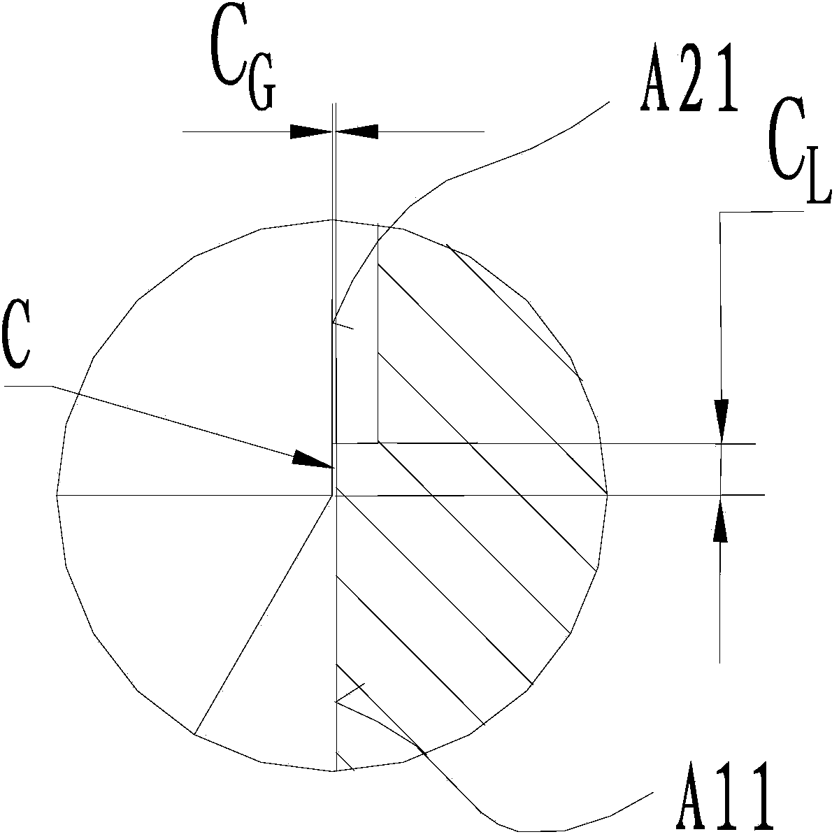
[0038] The throttling gap width of the throttle ring C between the first flange A11 and the second flange A21 is C G , wh...

Embodiment 2

[0041] The difference from Embodiment 1 is that the position of the throttle hole is different from the diameter of the throttle hole. Such as Figure 6-7 As shown, a first flange A11 is constructed on the inner wall near the head of the needle valve body A1, and the first flange A11 encloses an orifice; when the needle valve A2 is closed, the vertical inner wall of the first flange A11 Cooperate with the cylindrical outer wall of the needle valve A2 to form a throttle ring C; when the needle valve A2 is fully opened, there is no matching section between the vertical inner wall of the first flange A11 and the cylindrical outer wall of the needle valve A2 (that is, the throttle ring C disappears, does not work).

[0042]The advantage of the above structure is that the structure of the needle valve is not changed, and a throttle hole is constructed on the needle valve body. The diameter of the orifice is determined according to the diameter of the outer circle of the needle va...


PUM


Abstract

The invention discloses an oil spray nozzle of a fuel feed system oil sprayer. The oil spray nozzle comprises a needle valve body and a needle valve which are matched in a coupling mode. When the needle valve is closed, the inner wall of the needle valve body and the outer wall of the needle valve are matched to form a throttling ring with the throttling function, and the throttling ring is located between a tail coupling guide section and a head sealing conical surface of the oil spray nozzle. When the needle valve is completely opened, the throttling ring disappears and does not play a role. By carrying out the structural improvement and arranging the throttling ring at the non-sealed surface between the tail coupling guide section and the head sealing conical surface of the oil spray nozzle, control over the primary oil spraying speed is achieved, the closing response speed is increased, and machining is easily achieved. The invention further discloses the oil sprayer with the oil spray nozzle, and particularly discloses the electronic control oil sprayer. The ideal oil spraying speed can be achieved, the control strategy is simplified, the structure of the oil sprayer does not need to be changed, no additional devices need to be added, and the oil sprayer is suitable for application and popularization.

Description

technical field [0001] The invention relates to the field of fuel supply systems, in particular to a fuel injector of the fuel supply system and a fuel injector therein. Background technique [0002] In the fuel supply system, in order to optimize the combustion process of the fuel engine, control emissions and maintain good fuel economy, the fuel injection rate form of the injector is required to have a low initial fuel injection rate, a high main fuel injection rate and fast unloading rate, which is the ideal fuel injection rate. There are two forms of ideal fuel injection rate: initial fuel injection rate control and pre-injection control. Initial fuel injection rate control refers to appropriately reducing the fuel injection rate at the initial stage of fuel injection and reducing the fuel injection volume during the ignition delay period, which is generally achieved by changing the mechanical structure of the fuel injector or fuel injection pump. Pre-injection control...

Claims


Application Information

Patent Timeline
Patent Type & Authority Applications(China)
IPC IPC(8): F02M61/10
Inventor 张建明朱海抄罗兰连
Owner 北京天纬燃油喷射技术股份有限公司
Features
  • Generate Ideas
  • Intellectual Property
  • Life Sciences
  • Materials
  • Tech Scout
  • Unparalleled Data Quality
  • Higher Quality Content
  • 60% Fewer Hallucinations
Learn More