Multi-heat-source drying room system with geothermal pipe and double dehumidification devices

A technology of geothermal pipes and multiple heat sources, which is applied in the field of barn systems, can solve problems such as uneven heating, increased energy consumption, and energy waste, and achieve the effects of overcoming poor sustainability, improving thermal insulation performance, and improving utilization

Active Publication Date: 2014-09-24
上海邑腾节能环保设备有限公司
View PDF6 Cites 8 Cited by
  • Summary
  • Abstract
  • Description
  • Claims
  • Application Information

AI Technical Summary

Problems solved by technology

[0003] At present, the application of solar energy and air energy in the barn system is becoming more and more mature. However, in most of the barn systems today, the solar collectors are directly installed on the top of the barn, which is used as a heating system similar to electric heating. The heat source of the tube is used, which limits the location of the barn, and at the same time, the heating is uneven, which reduces the efficiency; the dehumidification function is mainly realized by the air energy system. When the solar energy is sufficient and the air energy is not needed, a good performance cannot be achieved. Dehumidification effect; because the evaporator of the air energy is located outdoors, it is easy to frost when the outdoor temperature is low and affects the use; when cooling or ventilating the barn, it is usually directly introduced into the outside air, so that the dryness in the barn It is not easy to maintain, and re-drying will increase energy consumption; when the heat provided by solar energy is greater than the required heat, it is often necessary to cool down at the same time or reduce the heat-absorbing area of ​​the solar device, which is inconvenient to use and causes energy waste

Method used


Image

  • Multi-heat-source drying room system with geothermal pipe and double dehumidification devices
  • Multi-heat-source drying room system with geothermal pipe and double dehumidification devices
  • Multi-heat-source drying room system with geothermal pipe and double dehumidification devices

Examples


Embodiment Construction

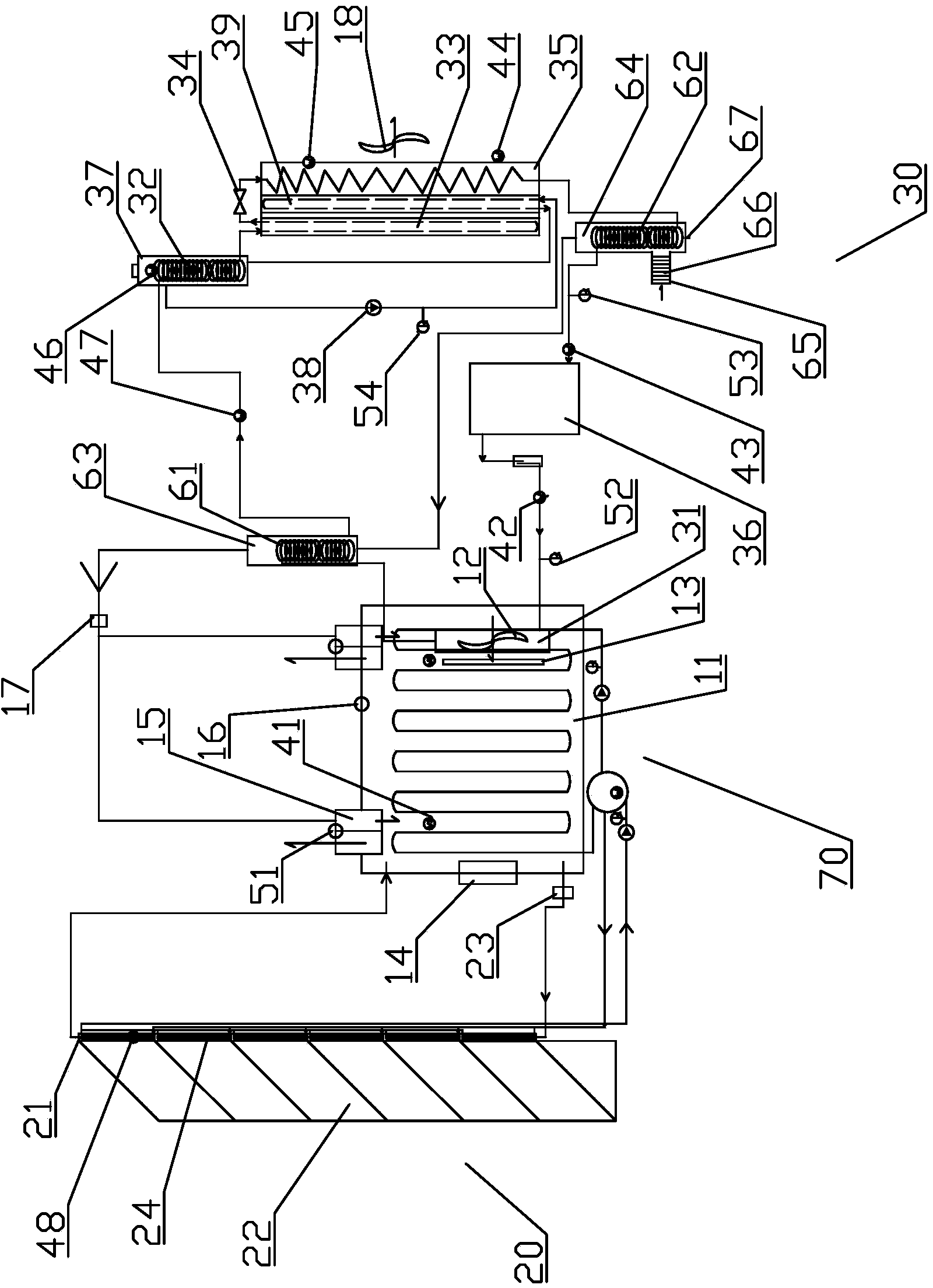
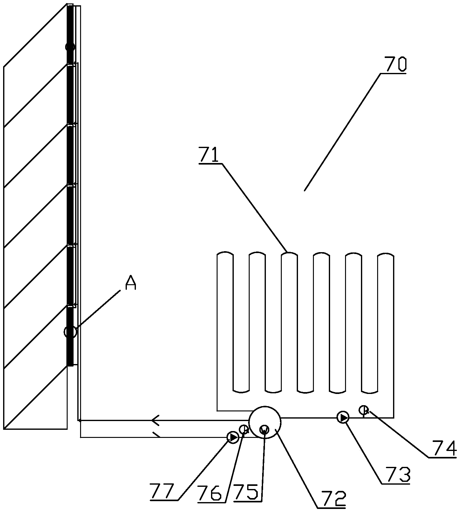
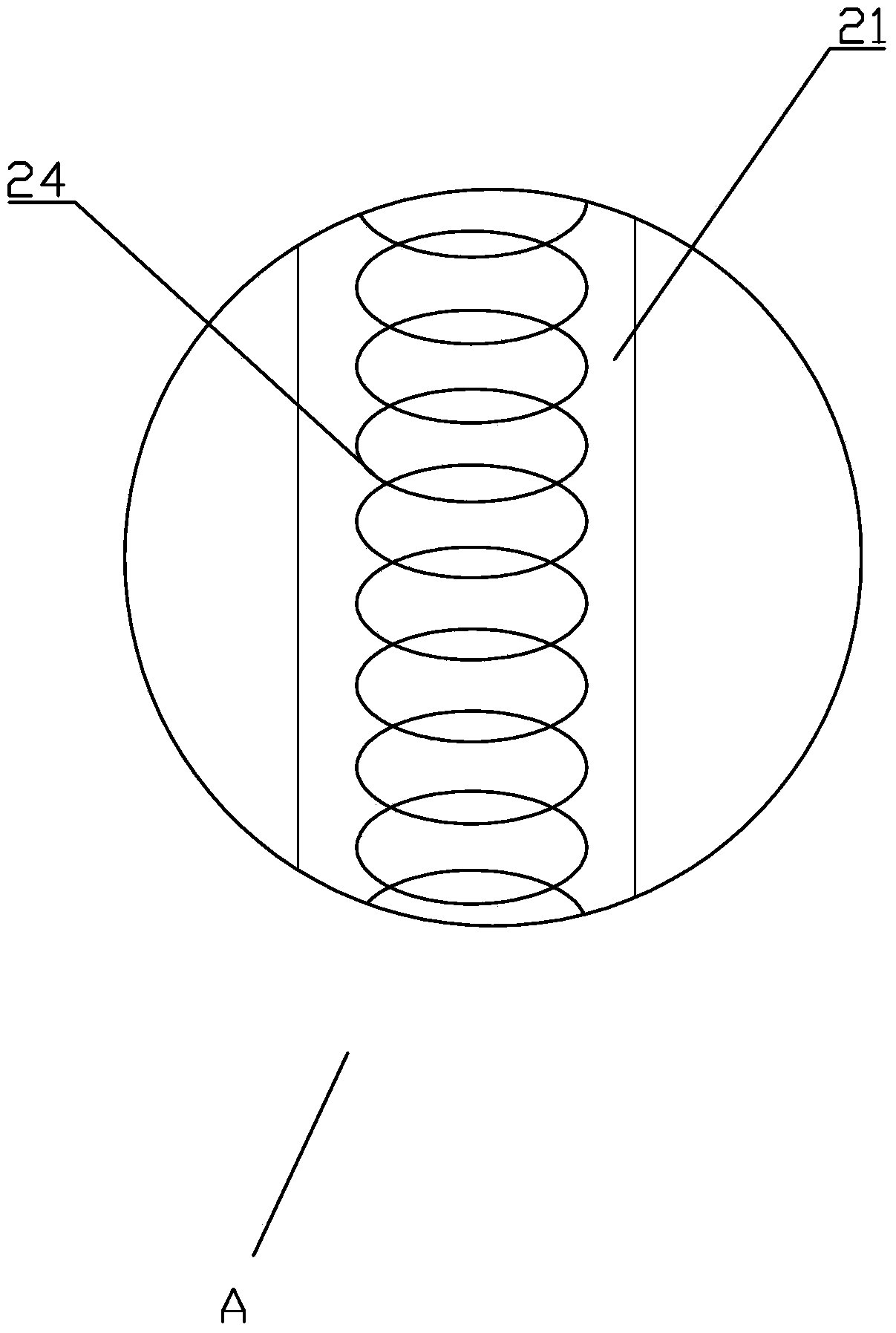
[0024] refer to figure 1 To Fig. 4, the barn system with multi-heat source belt geothermal pipes and double dehumidification devices includes: heat preservation barn 11; The heater 22 and the solar heat collection coil 24, wherein the solar air heat collector 21 communicates with the heat preservation barn 11 through pipes to form a fifth circulation loop, and the fifth circulation loop is driven by the third blower 23, and the solar heat collection coil 24 is arranged in the solar air heat collector 21, and the solar vacuum tube heat collector 22 is connected with the solar air heat collector 21 and the solar heat collection coil 24 at the same time; the air energy system 30 is used to collect air energy to heat the air, including The condenser 31, the air preheating coil 61, the waste heat recovery coil 32, the waste heat recovery heat exchanger 33, the intercepting device 34, the evaporator 35, the air condensing coil 62 and the compression machine 36, and the waste heat r...


PUM


Abstract

The invention discloses a multi-heat-source drying room system with a geothermal pipe and double dehumidification devices. The multi-heat-source drying room system adopts three heat sources, i.e. solar, air energy and electric heating pipes, to heat air inside a heat preservation drying room and comprises the independent dehumidification devices which do not depend on air energy and solar energy, a device for carrying out condensation dehumidification and preheating on air entering the drying room by utilizing air energy, and a geothermal device for storing and utilizing residual solar energy; and a defrosting device which utilizes air energy is added in an air energy system. According to the invention, the defect of instability of solar energy is overcome, the utilization rate of solar energy is effectively improved, the multi-heat-source drying room system is energy-saving and environmental-friendly, has a wide application range and can be suitable for the cold environment, and the temperature and the humidity in the drying room can be effectively kept.

Description

technical field [0001] The invention relates to a barn system for dehumidification and drying of wood, medicinal materials, grains, food, seafood, tobacco leaves, etc., especially a barn system using solar energy and air energy with multiple heat sources, geothermal pipes and double dehumidification devices system. Background technique [0002] Solar energy has the advantages of low cost of use, energy saving and environmental protection, and huge energy, but it also has the disadvantage of instability because of its discontinuity and dependence on the weather, so it needs to be used in conjunction with other heat sources. Air energy is a low-quality heat energy, which needs to be converted into high-quality usable heat energy with a small amount of electric energy to drive the compressor. Compared with ordinary electric heating methods, it still has the advantages of low cost, energy saving and environmental protection. In the current situation of conventional energy short...

Claims


Application Information

Patent Timeline
Patent Type & Authority Applications(China)
IPC IPC(8): F26B9/00F26B21/00F26B23/00F24J2/00F24J2/24F24H4/06F24S10/70
CPCY02E10/44Y02P60/85Y02P70/10
Inventor 刘毅
Owner 上海邑腾节能环保设备有限公司
Why Eureka
Try Eureka