Remote displacement measurement system based on position sensor

A technology of displacement measurement and displacement sensor, which is applied in the direction of measuring devices, instruments, and optical devices, etc. It can solve the problems of being easily disturbed by environmental factors and low detection accuracy of feedback optical signals, and achieves simple installation and debugging process and improved reliability. , The effect of improving the measurement accuracy

Active Publication Date: 2014-09-24
BEIJING INST OF SPACE LAUNCH TECH +1
View PDF2 Cites 7 Cited by
  • Summary
  • Abstract
  • Description
  • Claims
  • Application Information

AI Technical Summary

Problems solved by technology

[0006] The purpose of the present invention is to provide a long-distance displacement measurement system based on a position sensor to solve the technical problems that the optical signal detection circuit in the existing collimator has low detection accuracy of the feedback optical signal and is easily disturbed by environmental factors

Method used


Image

  • Remote displacement measurement system based on position sensor
  • Remote displacement measurement system based on position sensor
  • Remote displacement measurement system based on position sensor

Examples


Embodiment Construction

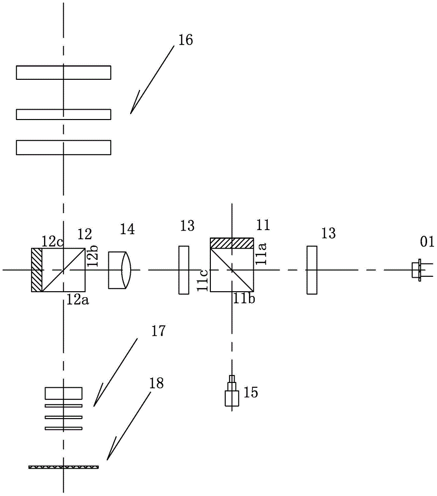
[0021] This embodiment utilizes that the horizontal section of the cubic prism is a rectangle. In this embodiment, a fixed plane of the cubic prism is arranged on the base, and the other three planes that are sequentially connected clockwise are the first transmission surface, the incident surface and the second plane. transmissive surface.

[0022] Such as figure 1 As shown, the embodiment includes a telescopic (mirror) part, wherein an objective lens group 16 and an eyepiece group 17 form an optical axis along the focal length of the lens, and also includes a first cube prism 11, a second cube prism 12, a laser emitter 15 and a PSD displacement Sensor 01, the incident surface 11b of the first cubic prism 11 is perpendicular to the incident surface 12b of the second cubic prism 12; the first transmission surface 11a and the second transmission surface 11c of the first cubic prism 11, and the incidence Face 12b is coaxial with the fixed plane, and the incident face 12b of the...


PUM


Abstract

A remote displacement measurement system based on a position sensor comprises a telescoping part and a signal processing part, an objective lens set and an eye lens set form an optical axis along the focal length of a lens, a first block prism, a second block prism, a laser transmitter and a PSD displacement sensor are further included, and the incident plane of the first block prism is perpendicular to that of the second block prism. The first transmission face and the second transmission face of the first block prism are coaxial with the incident plane and the fixed plane of the second block prism, and the incident plane of the second block prism is opposite to the second transmission face of the first block prism. The first transmission face and the second transmission face of the second block prism are coaxial with the optical axis, the first transmission face of the second block prism faces the objective lens set, the laser axis of the laser transmitter is coaxial with the incident plane of the first block prism, and the light receiving face of the PSD displacement sensor is opposite to the first transmission face of the first block prism. Measurement precision is greatly improved, and feedback signals are not prone to being influenced by environmental factors.

Description

technical field [0001] The invention relates to a signal measurement system, in particular to a measurement system for long-distance displacement signals. Background technique [0002] Aiming and collimation operation is a key action in the process of rocket launch. Its purpose is to adjust the normal direction of the prism on the platform of the arrow to the shooting direction by means of photoelectric self-collimation before the rocket launch, so as to ensure the initial orientation accuracy of the rocket, so that The rocket is in the exact take-off orientation prior to launch. [0003] Generally, by installing photoelectric transmitting and receiving components on the body of the collimator, the collimating light source uses a red light diode, and the receiving device uses a photosensitive triode. The aiming signal amplifier amplifies the received photoelectric signal, and finally indicates the deflection direction and size of the platform prism in the form of a pointer ...

Claims


Application Information

Patent Timeline
Patent Type & Authority Applications(China)
IPC IPC(8): G01B11/02
Inventor 范毅王华生王岩李发动狄世超宋小艳贺长水贺永喜
Owner BEIJING INST OF SPACE LAUNCH TECH
Why Eureka
Try Eureka