Image blur processing method and device
A fuzzy processing and image technology, applied in image data processing, graphics and image conversion, instruments, etc., can solve problems such as poor adaptability and slow fuzzy processing operation speed, and achieve high computing speed, good adaptability, and resource saving. Effect
- Summary
- Abstract
- Description
- Claims
- Application Information
AI Technical Summary
Problems solved by technology
Method used
Image
Examples
Embodiment 1
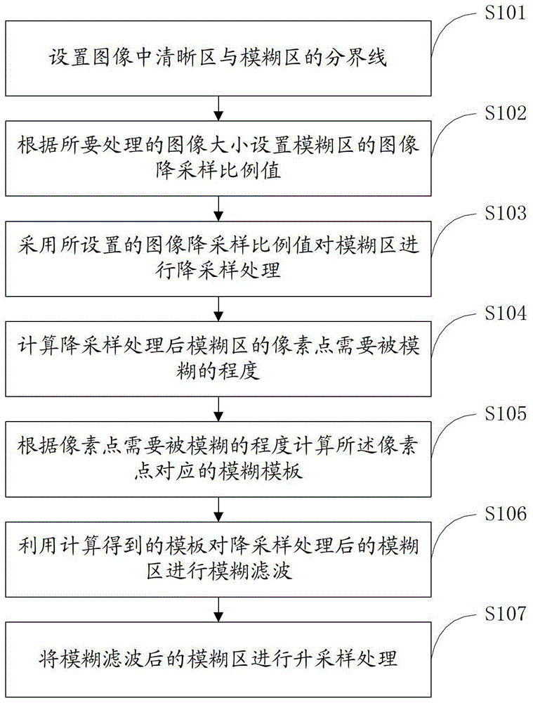
[0042] refer to figure 1 The flow chart of the image blurring processing method shown will be described in detail through specific steps below.
[0043] S101, setting a boundary line between a clear area and a blur area in an image.
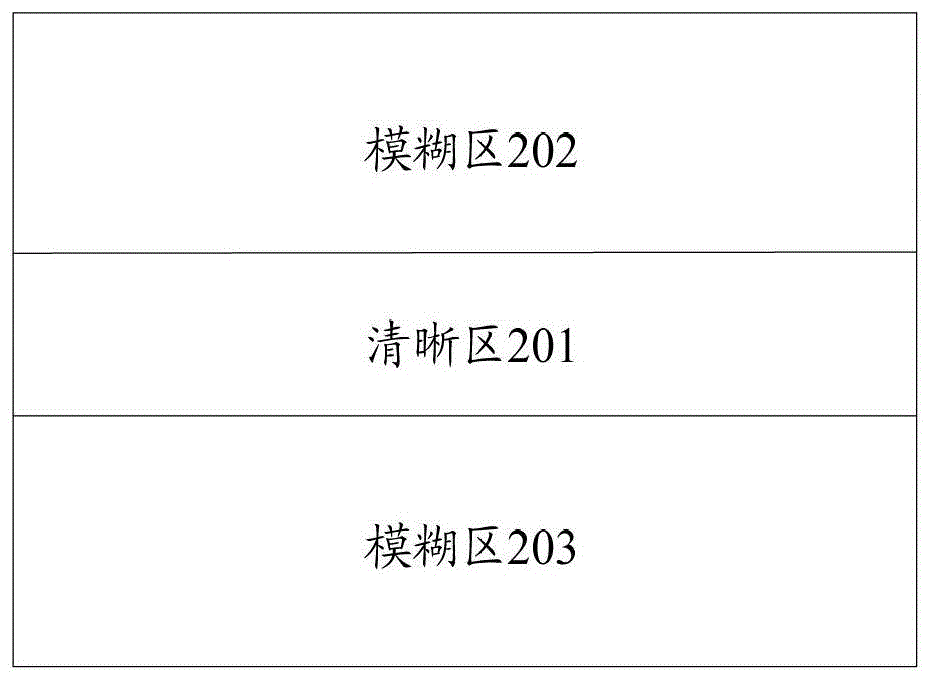
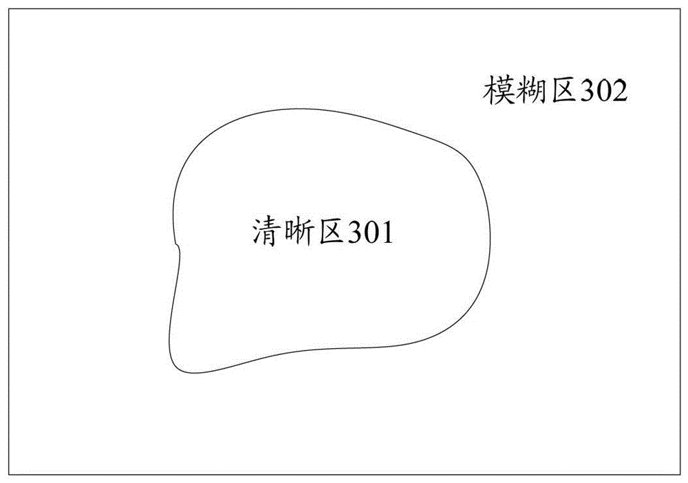
[0044] The miniature landscape blurred special effect image to be processed in this embodiment is composed of a clear area in the middle and one or more blurred areas around, and the set dividing line can be a closed curve. refer to figure 2 and image 3 The schematic diagram of the layout of the miniature landscape special effect image shown, wherein, figure 2 Among them, the middle part is the clear area 201, and the upper and lower parts are the fuzzy area 202 and the fuzzy area 203 that need to be gradually blurred from the boundary line with the clear area to the outside, and image 3 In the middle, there is a clear area 301 in the middle, the boundary line is a curve, and the surrounding area is a fuzzy area 302 that gradually becomes...
Embodiment 2
[0075] The difference from Embodiment 1 is that this embodiment also uses the set pixel point sampling interval to sample the pixels in the blurred area, that is, combining two processing methods of downsampling in the blurred area of the image and sampling the pixels in the blurred area. Refer to Figure 5 The shown flow chart of the image blurring processing method specifically includes the following steps:
[0076] S501. Preprocessing the image to enhance the sense of model of the image.
[0077] As mentioned above, in order to enhance the model sense of the image, various processing can be performed on the image, for example, the brightness, saturation, and contrast of the image can be adjusted, and the edge of the image in the clear area can also be enhanced at the same time or only, so I won’t go into details here . The above-mentioned process of enhancing the model sense of the image may also be performed after blurring the image.
[0078] S502, setting a boundary l...
Embodiment 3
[0109] refer to Figure 8 The shown image blur processing device includes: a boundary line setting unit 801, a sampling blur parameter setting unit 802, a sampling blur processing unit 803, a blur template calculation unit 804 and a blur filter unit 805, wherein:
[0110] A boundary setting unit 801, configured to set the boundary between the clear area and the blurred area in the image;
[0111]A sampling blur parameter setting unit 802, configured to set the sampling blur parameters of the blur area according to the size of the image to be processed;
[0112] A sampling blur processing unit 803, configured to perform sampling blur processing on the blur area by using the set sampling blur parameters of the blur area;
[0113] A fuzzy template calculation unit 804, configured to calculate and determine a fuzzy template corresponding to pixels in the fuzzy area;
[0114] The blur filtering unit 805 is configured to use the blur template obtained by the blur template calculat...
PUM
 Abstract
Description
Claims
Application Information
 - R&D
- Intellectual Property
- Life Sciences
- Materials
- Tech Scout
- Unparalleled Data Quality
- Higher Quality Content
- 60% Fewer Hallucinations
Browse by: Latest US Patents, China's latest patents, Technical Efficacy Thesaurus, Application Domain, Technology Topic, Popular Technical Reports.
© 2025 PatSnap. All rights reserved.Legal|Privacy policy|Modern Slavery Act Transparency Statement|Sitemap|About US| Contact US: help@patsnap.com


