A camera resolution test device and method

A test device and camera technology, applied in image communication, television, electrical components, etc., can solve problems such as inaccurate test results, inability to adjust, and decreased contrast of black and white stripes, so as to avoid inhomogeneity of emitted light and avoid inaccuracy factors, the effect of test results being accurate

Inactive Publication Date: 2016-08-24
XI'AN INST OF OPTICS & FINE MECHANICS - CHINESE ACAD OF SCI
View PDF5 Cites 0 Cited by
  • Summary
  • Abstract
  • Description
  • Claims
  • Application Information

AI Technical Summary

Problems solved by technology

When the camera has a fixed focal length and a fixed aperture, the focal length and aperture cannot be adjusted, and this standard is no longer applicable; when the distance between the camera and the test chart is adjusted, the border defined by the arrow of the test chart can be achieved and the monitor is displayed in the underscan mode. The edges of the image are exactly the same, but because the measurement standard does not limit and explain the camera distance, the number of black and white bars that can be distinguished at this time can no longer be used as the real measurement result
Moreover, when the video signal system of the camera is different and the aspect ratio of the output image of the camera is different, the test chart needs to be replaced, which is inconvenient to test
Secondly, the test tools stipulated in the standard are mainly test charts drawn on hard paper. After long-term use, the paper material will be damp, oxidized and yellowed, the reflectivity of the test chart will change, and the contrast of black and white stripes will decrease. , resulting in inaccurate test results
In addition, the method specified in the test standard is to subjectively judge the narrowest stripes that can be distinguished by human eyes, with human subjective factors and objective factors of the body, the test results cannot be accurately quantified

Method used


Image

  • A camera resolution test device and method

Examples


Embodiment Construction

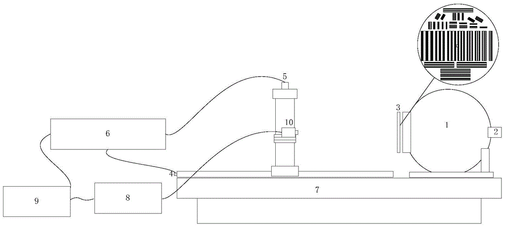
[0038] In order to achieve accurate testing of the camera resolution, the present invention uses a large field of view integrating sphere to achieve light source output, and a transmissive multi-group fringe discrimination rate board is placed at the light exit of the integrating sphere, and the camera is fixed on a long guide rail. Adjust the camera distance, use the computer to collect the output image of the camera and determine the narrowest stripe width that the camera can distinguish, so as to realize the accurate test of the resolution of the camera under any output format at a certain focal length and a certain camera distance.

[0039] Attached below figure 1 , The device of the present invention is described in detail:

[0040] A camera resolution test device, comprising an optical stabilization platform 7, an image acquisition unit 8, a computer 9, and a large field of view integrating sphere 1, an integrating sphere light source 2, and a transmissive multi-group fringe ...


PUM


Abstract

The invention belongs to the field of camera performance evaluation and testing, and in particular relates to a camera resolution testing device and method. The present invention adopts a large field of view integrating sphere to realize light source output, places a transmissive multi-group fringe discrimination rate board at the light outlet of the integrating sphere, sets the tested camera on an optically stable platform, and adjusts the shooting distance of the tested camera, using the image The acquisition unit collects the output image of the camera under test and uploads it to the computer, and the computer interprets the horizontal resolution and vertical resolution of the camera under test, so as to realize the accuracy of the resolution of the camera under any output system at a certain focal length and a certain camera distance. test.

Description

Technical field [0001] The invention belongs to the field of camera performance evaluation and testing, and specifically relates to a camera resolution testing device and method. Background technique [0002] With the continuous development of my country's military, aviation and aerospace industries, in order to observe and analyze the remote measurement parameters of the mission execution process, each aircraft product is equipped with missile-borne, arrow-borne, airborne and spaceborne cameras. [0003] In order to achieve clear imaging of the observation target and accurate collection of telemetry information, the resolution test of the camera is necessary. [0004] The resolution of the camera is also called sharpness or resolution, including the horizontal resolution and the vertical resolution, which describe the resolution of the target details in the horizontal and vertical directions of the camera output image. The vertical resolution of the camera refers to the number of h...

Claims


Application Information

Patent Timeline
Patent Type & Authority Patents(China)
IPC IPC(8): H04N17/00
Inventor 龙江波赵建科李坤段亚轩曹昆田留德
Owner XI'AN INST OF OPTICS & FINE MECHANICS - CHINESE ACAD OF SCI
Why Eureka
Try Eureka