
Reductant aqueous solution mixing device and exhaust gas post-treatment device equipped with it

A technology of mixing device and aqueous solution, which is applied in the direction of exhaust gas treatment, noise reduction device, exhaust device, etc., can solve the problems such as easy retention of urea aqueous solution and difficult detour of exhaust gas, achieve good thermal insulation performance, prevent leakage of exhaust gas, and meet thermal insulation performance Effect

Active Publication Date: 2015-09-16
KOMATSU LTD
View PDF11 Cites 0 Cited by
  • Summary
  • Abstract
  • Description
  • Claims
  • Application Information

AI Technical Summary

Problems solved by technology

[0013] In order to prevent this problem, it is also conceivable to further install a heat insulating material so as to cover the front end of the bolt, but in this case, there will be a height difference between the heat insulating material and the nozzle, so it is difficult for the exhaust gas to detour to the nozzle side, and the urea aqueous solution Easy to get stuck, which is not desired

Method used


Image

  • Reductant aqueous solution mixing device and exhaust gas post-treatment device equipped with it
  • Reductant aqueous solution mixing device and exhaust gas post-treatment device equipped with it
  • Reductant aqueous solution mixing device and exhaust gas post-treatment device equipped with it

Examples


Embodiment Construction

[0034] Hereinafter, one embodiment of the present invention will be described based on the drawings.

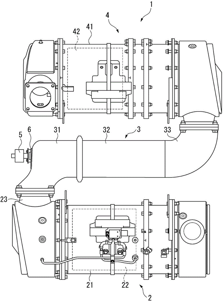
[0035] exist figure 1 A plan view of the exhaust gas post-treatment device 1 according to the present embodiment is shown in . In the following description, "upstream" means the upstream side in the flow direction of exhaust gas, and "downstream" means downstream in the flow direction of exhaust gas.

[0036] exist figure 1 Among them, the exhaust gas post-treatment device 1 includes a diesel particulate filter (Diesel particulate filter, hereinafter referred to as "DPF") device 2 as a filter device, a reducing agent aqueous solution mixing device (hereinafter , referred to as "mixing device") 3 and selective reduction catalyst (Selective Catalytic Reduction, hereinafter referred to as "SCR") device 4. These devices 2 to 4 are provided in the middle of an exhaust pipe through which exhaust gas from a diesel engine (not shown) flows. In addition, in the case of constructio...


PUM


Abstract

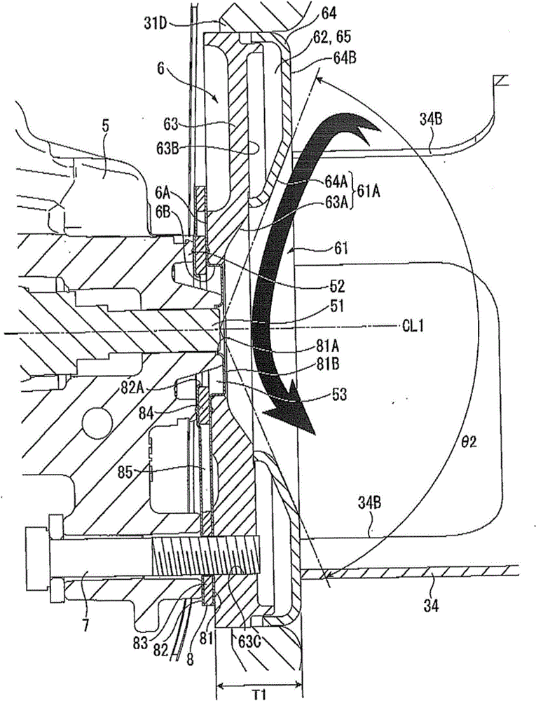
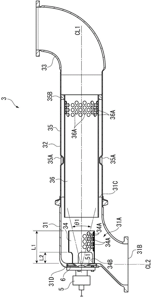
A mixing device includes: an elbow pipe attached to an outlet pipe of a filter device; a straight pipe connected to a downstream side of the elbow pipe; and an injector attached to the elbow pipe and injecting a reductant aqueous solution into an inside of the elbow pipe toward the straight pipe. The elbow pipe is provided with an injector attachment to which the injector is attached with a bolt. An attachment face of the injector attachment is substantially flush with an end of an injection nozzle of the injector. The injector attachment is provided with a recess at which an end of the injection nozzle is exposed, the recess being enlarged toward the straight pipe. A heat-insulation layer located near an outer periphery of the recess is provided inside the injector attachment. An end of the bolt penetrates the injector from an outside to reach the heat-insulation layer.

Description

technical field [0001] The present invention relates to a reducing agent aqueous solution mixing device and an exhaust gas post-treatment device equipped with the same, and relates to a reducing agent aqueous solution mixing device used when purifying exhaust gas by supplying a reducing agent aqueous solution such as an aqueous urea solution to a selective reduction catalyst, and an exhaust gas equipped with the same Aftertreatment device. Background technique [0002] Conventionally, there is known an exhaust gas aftertreatment device that purifies nitrogen oxides (NOx) contained in engine exhaust gas using a selective reduction catalyst (hereinafter referred to as "SCR"). Such an SCR is supplied with an aqueous urea solution injected from an injector. The injector is installed as part of a mixing device provided upstream of the SCR (for example, Patent Document 1). A urea aqueous solution is injected from the injector into the exhaust gas flowing in the mixing device, an...

Claims


Application Information

Patent Timeline
Patent Type & Authority Patents(China)
IPC IPC(8): F01N3/08F01N3/36
CPCF01N2610/02F01N3/208F01N13/1827F01N3/10Y02T10/24F01N2470/02F01N2610/1453F01N2240/20Y02T10/12F01N3/035F01N3/28
Inventor 加藤隆志富冈裕之伊东木
Owner KOMATSU LTD
Learn More