squeeze water mop

A mop and mop rod technology, applied in the field of mops, can solve the problems of damage, some of which break within a month or two, limited tensile and bending strength of plastic parts, large volume and weight of the mop head, etc., to overcome weather resistance Poor performance, good positioning and guiding effect, weight reduction effect

Inactive Publication Date: 2017-02-22
丁正栓
View PDF6 Cites 0 Cited by
  • Summary
  • Abstract
  • Description
  • Claims
  • Application Information

AI Technical Summary

Problems solved by technology

However, the structure of the water squeezing mechanism of this type of mop is complicated, and it can only be manufactured by injection molding at present. Due to the limited tensile and bending strength of the plastic parts, the water squeezing pressure is not large, so the entire strip cleaning block must be completely Only when the mop enters the inverted U shape can the water be squeezed, and the lower end surface of the inverted U-shaped groove mop seat is slid and installed with a folded plate, and the folded plate is slid and connected with the structure of the water squeezed plate, through two sets of The sliding mechanism allows the cleaning block to be completely enclosed in the folded plastic panel
Since the plastic mop seat needs to fully accommodate the entire cleaning block when squeezing water, its plastic wall thickness and size need to be made very large, resulting in a large volume and weight of the entire mop head, making it difficult to clean in a narrow space, such as the common The floor inside the foot of the bed and the foot of the cabinet is inaccessible
[0004]Moreover, there are many parts in the whole set of water squeezing mechanism. When the temperature reaches below zero in winter, the plastic becomes brittle and easy to break. In long-term use, ultraviolet rays will also make it aging and brittle. Because these parts receive a large external force during the water squeezing operation, they will undergo a certain elastic deformation. After the plastic is aged and brittle, it is easy to break during the water squeezing process, and the damage of any part will cause the failure of the entire mechanism.
As a result, the durability of the existing squeeze mop is insufficient. Although the cleaning block can be replaced at any time as a consumable, the plastic squeeze mechanism will usually be damaged after about one year of use, and some will break within one or two months. At that time, not only will it cost money When buying a new mop, the plastic collodion mop can only be of one size in use (the collodion mop head cannot be changed in size), and the discarded old mop will also cause environmental pollution

Method used


Image

  • squeeze water mop
  • squeeze water mop
  • squeeze water mop

Examples


Embodiment 1

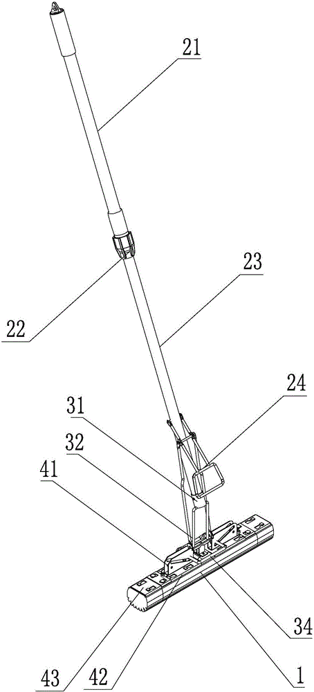
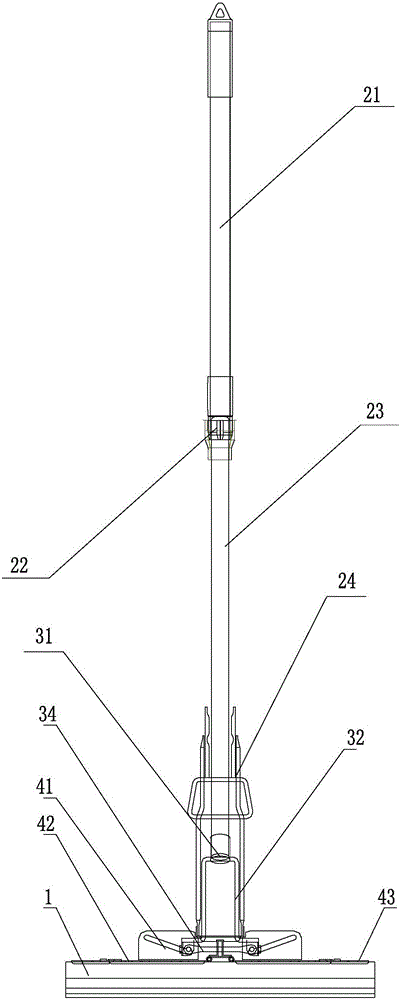
[0035] The squeeze mop of the present embodiment is as figure 1 , figure 2 and image 3 As shown, it includes a mop head 1 and a mop rod, wherein the mop head 1 is a strip made of collodion, and the mop rod is relatively fixed by the upper rod body 21 and the lower rod body 23 that are nested with each other through the bundle sleeve 22 . A fixed sleeve 31 is installed at the bottom of the lower rod body 23, and a main frame 32 formed by bending a metal bar is welded on the fixed sleeve 31. The main frame 32 is door-shaped and has a beam and two columns, wherein the beam and the fixed sleeve 31 welding, the bottom of the column is welded with a pair of sliders, the column is covered with a sliding sleeve 33, the two sides of the sliding sleeve 33 are connected to the handle 24 on the mop rod through the pull rod, and the bottom of the sliding sleeve 33 is fixedly connected with the center plate 36 A pair of splints 42 are hinged on both sides of the center plate 36, the mop...

Embodiment 2

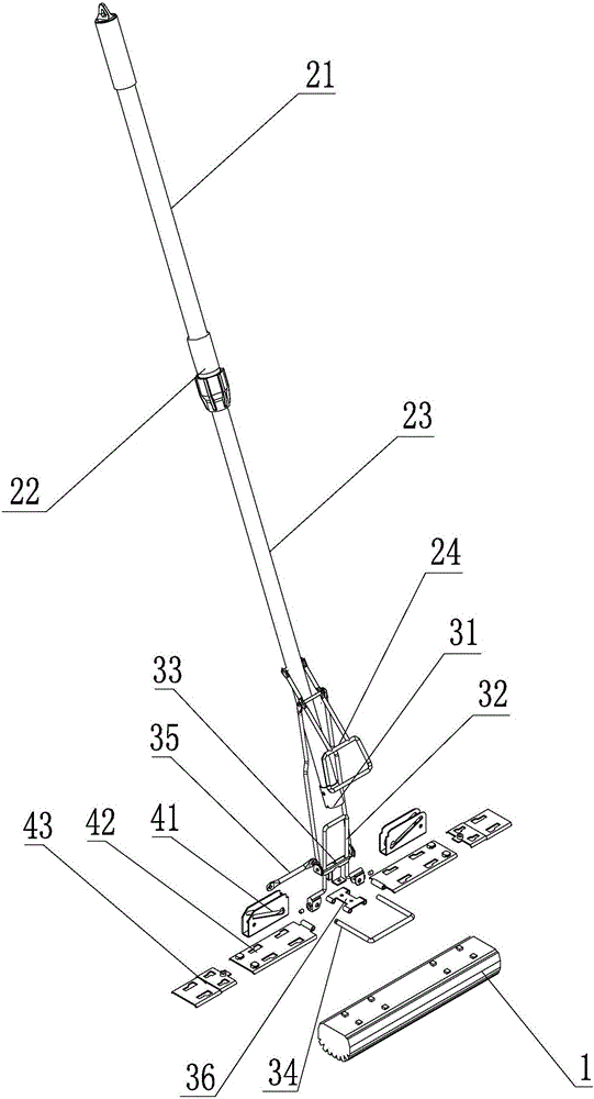
[0041] The squeeze mop of the present embodiment is as Figure 6 , Figure 7 and Figure 8 As shown, it includes a mop head 1 and a mop rod 2, wherein the mop head 1 is a strip made of collodion. There is a handle 21 at the bottom of the mop rod 2, and a main frame 32 is installed at the bottom end of the mop rod. The main frame 32 is punched into a door shape by sheet metal, and has two uprights and a crossbeam on the top. Sleeved on the bottom end of the mop rod 2. The top plate of the beam is provided with a guide hole for passing through the pull rod 33 , and the bottom end of the pull rod 33 is fixedly connected with the central plate 35 and the cover plate 34 . A pair of splints 42 are hinged on both sides of the center plate 35. The mop head 1 is clamped under the splint 42. The back of the splint 42 is welded with a chute seat 41. The chute seat 41 has two parallel vertical plates. Between, and slidingly match with the chute on the vertical plate through the pin s...


PUM


Abstract

The invention discloses a mop with a water squeezing function. The mop comprises a mop rod and a mop head. The mop head is arranged on a pair of clamping plates in a clamped mode. Both the clamping plates are hinged to a central plate. The central plate is connected with a handle on the mop rod. A main framework is arranged between the mop rod and the clamping plates and comprises two stand columns and a beam. A hinge pin is arranged at the bottom end of each stand column in a penetrating mode. The beam is fixedly connected to the bottom end of the mop rod. Each hinge pin is in slide fit with a slide groove base outside the corresponding stand column. Each slide groove base is provided with two stand plates and a bottom plate. A slide groove is formed in each stand plate. The bottom plates are fixedly connected with the clamping plates. When the mop is used, the clamping plates are opened and located in the same straight line together with the central plate. In the water squeezing process, the slide groove bases surround the stand columns, lead the clamping plates to be closed and enter the main framework. According to the mop, by optimizing the structure of the main framework and the slide groove bases, metal pieces manufactured through stamping, bending, stretching and welding can be adopted for the mop, the structural strength and the water squeezing capacity are improved, and the mop has the remarkable advantages of being high in compactedness and durability.

Description

technical field [0001] The invention relates to a mop, in particular to a water-squeezing mop that squeezes a pair of splints inwards through a pull rod to realize dehydration. Background technique [0002] The traditional mop mainly has a mop head and a mop rod. The mop head needs to be wrung out after cleaning, and usually needs to be dehydrated with the help of an external squeezing device. It is very inconvenient to carry these special squeezing devices at the same time when mopping the floor. . [0003] Chinese patent CN201275036Y discloses a water-squeezing mop. As long as the handle is pulled upwards, the splint hinged at the bottom of the mop is turned over by the pull rod to the inside of the water-squeezing mechanism, and the cleaning block in the middle is squeezed to complete the water-squeezing action. However, the structure of the water squeezing mechanism of this type of mop is complicated, and it can only be manufactured by injection molding at present. Due ...

Claims


Application Information

Patent Timeline
Patent Type & Authority Patents(China)
IPC IPC(8): A47L13/20A47L13/258
Inventor 丁正栓
Owner 丁正栓
Why Eureka
Try Eureka