Driven-by-wire brake system for electric automobile

A technology of brake-by-wire and electric vehicles, applied in the direction of brakes, brake components, brake transmission devices, etc., can solve the problems that the motor speed cannot reach the rated speed in an instant, the system response lags, and the braking safety is difficult to guarantee. The effect of reducing speed and power requirements, improving control accuracy, and improving braking safety

Active Publication Date: 2014-10-01
TSINGHUA UNIV +1
View PDF6 Cites 22 Cited by
  • Summary
  • Abstract
  • Description
  • Claims
  • Application Information

AI Technical Summary

Problems solved by technology

[0004] However, since the system only uses the motor to provide the braking force, the motor is directly connected to the ball screw mechanism, and there is no other reduction mechanism in between, the speed of the motor cannot reach the rated speed instantly when starting, so the system has a large response lag problem. Reaching the r

Method used


Image

  • Driven-by-wire brake system for electric automobile

Examples


Example Embodiment

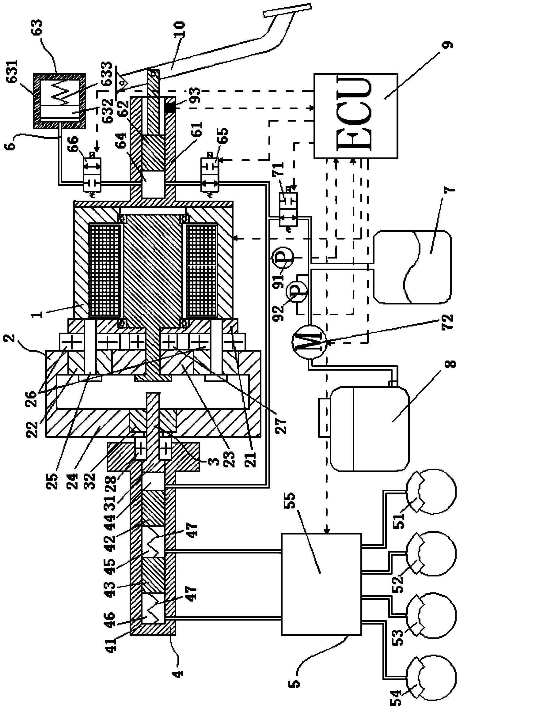
[0012] The present invention will be described in detail below with reference to the drawings and embodiments.

[0013] Such as figure 1 As shown, the present invention includes a motor 1, a planetary gear train 2, a threaded screw pair 3, a master cylinder 4, a braking mechanism 5, a pedal execution and simulation mechanism 6, an accumulator 7, an oil A pot 8 and a controller 9.

[0014] The planetary gear train 2 includes a planet carrier 21 that is firmly connected to the front end housing of the motor 1, a plurality of planet wheels 22 that are rotatably connected to the planet carrier 21, and a planetary gear that is firmly connected to the output shaft of the motor 1 and is connected to each planetary wheel. 22 meshing sun gear 23 and a ring gear 24 meshing with each planetary gear 22.

[0015] The threaded screw 3 includes a screw 31 and a nut 32 connected to the screw 31 by threads, and the nut 32 is coaxially fastened and connected to the front end of the ring gear 24.

[0...


PUM


Abstract

The invention relates to a driven-by-wire brake system for an electric automobile. The driven-by-wire brake system comprises a motor, a planetary gear train, a thread lead screw pair, a main cylinder, a brake mechanism, a pedal execution and simulation mechanism, an energy accumulator, an oil pot and a controller. The motor, a speed reduction and torque increase mechanism and the thread lead screw pair are used for replacing a vacuum booster of a traditional vacuum servo hydraulic braking system, a piston in the brake main cylinder is pushed to move to generate brake hydraulic pressure, and therefore dependence on the vacuum degree of an engine is eliminated. The high-pressure energy accumulator is arranged, driving pressure compensation is provided for the system in the initial brake process of the motor, the response time of a traditional automobile brake system can be achieved easily, the control precision of the system is improved, and the requirements of the system for the rotating speed and power of the drive motor can be effectively reduced by being matched with the speed reduction function of the planetary gear train. The high-pressure energy accumulator can provide braking two to three times when the system breaks down and is overall powered off, meanwhile, pedal force provided by people can act on braking at the moment at the same time, and therefore the brake safety of the system is improved.

Description

technical field [0001] The invention relates to a braking system, in particular to a wire-controlled braking system for an electric vehicle. Background technique [0002] With the increasingly serious resource crisis, new energy vehicles such as hybrid vehicles and electric vehicles have gradually become research hotspots. At the same time, new requirements have been put forward for the braking systems of hybrid vehicles and electric vehicles. In order to achieve good cooperation with the regenerative braking system of hybrid electric vehicles and electric vehicles, and to make the regenerative braking system recover as much braking energy as possible on the basis of braking safety, the dependence on engine vacuum should first be reduced or eliminated , Secondly, it can quickly and accurately compensate for insufficient braking without affecting the feeling of the brake pedal. At the same time, the volume of the braking system should be reduced as much as possible to facilit...

Claims


Application Information

Patent Timeline
IPC IPC(8): B60T13/66B60T13/74B60T17/00
Inventor 于良耀刘晓辉王治中张永生魏文若
Owner TSINGHUA UNIV
Why Eureka
Try Eureka