Throttling adjusting system of cogeneration turbine unit and method of ordering power by heat

A technology for adjusting systems and steam turbine units, which is applied in mechanical equipment, engine components, machines/engines, etc., and can solve the problem of high limit setting value of extraction butterfly valve, inability to guarantee measurement accuracy, and inability to achieve thermostatic electricity for thermoelectric units, etc. problem, to achieve the effect of high flow efficiency

Active Publication Date: 2015-07-15
STATE GRID CORP OF CHINA +1
View PDF8 Cites 0 Cited by
  • Summary
  • Abstract
  • Description
  • Claims
  • Application Information

AI Technical Summary

Problems solved by technology

In some power plants, in order to ensure the safety of the blades of the low-pressure cylinder, the limit setting value of the extraction disc valve is too high, and the opening of the extraction disc valve in some power plants is about 25%, that is, it cannot continue to close downwards, resulting in the extraction steam flow cannot be guaranteed during the load reduction process
[0003] At the same time, in order to reduce the main steam pressure loss of the existing heating units above 300MW, no throttling device is installed on the main steam pipeline to measure the main steam flow, which cannot guarantee the measurement accuracy
Due to the influence of safety and measurement accuracy, it has not been possible to determine the power of thermoelectric units by heat

Method used


Image

  • Throttling adjusting system of cogeneration turbine unit and method of ordering power by heat
  • Throttling adjusting system of cogeneration turbine unit and method of ordering power by heat
  • Throttling adjusting system of cogeneration turbine unit and method of ordering power by heat

Examples


Embodiment 1

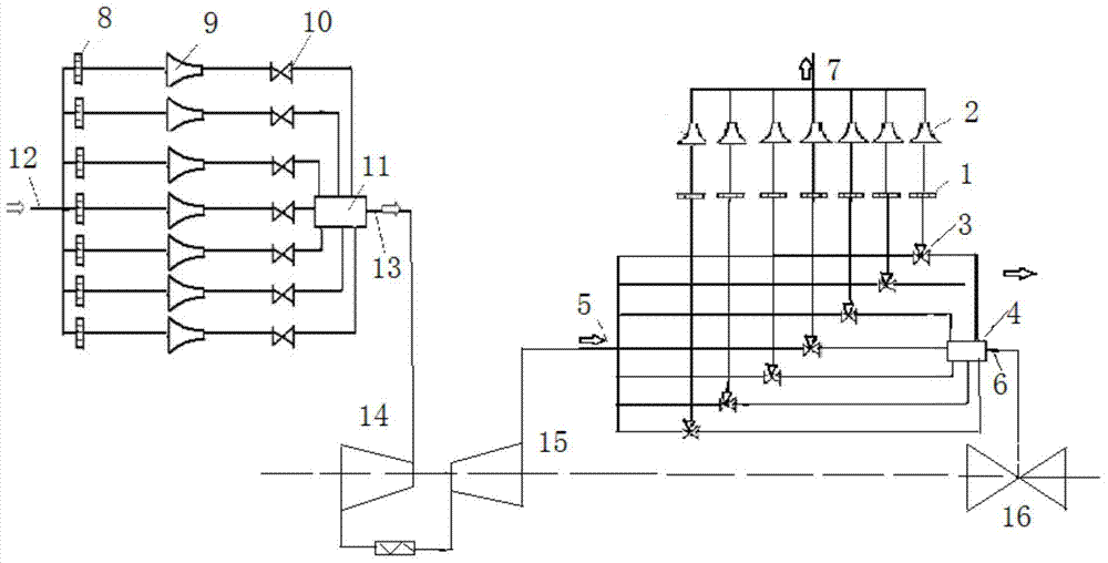
[0048] For a subcritical 300,000-kilowatt pure condensing unit, the power plant entrusted the manufacturer to carry out the transformation using the national coal-fired unit comprehensive upgrading and transformation fund. The high-pressure cylinder removed the regulating stage, and the steam distribution mechanism was developed based on the patented technology (Patent No. ZL201320280254.4) throttle valve system. The associated steam extraction adjustment valve is installed on the medium and low pressure connecting pipe. The heat consumption rate of the rated working condition assessment test before the transformation was 8105, and the measured heat consumption rate of the pure condensing condition after the transformation was 7950kJ / kWh, the efficiency of the high-pressure cylinder reached 86%, and the pressure loss of the steam distribution mechanism was less than 0.5%. The design value has been achieved after transformation; especially at 60% low load, the unit operates at ...


PUM


Abstract

The invention discloses a throttling adjusting system of a cogeneration turbine unit and a method of ordering power by heat of the throttling adjusting system. The system comprises a plurality of channels that are connected in parallel to a heat-removing network steam-supply pipe; each channel comprises a flow rate adjuster, a flow rate nozzle and a three-way valve which are connected in sequence; one end of a three-way valve of each channel is connected in parallel with a medium-pressure cylinder steam outlet pipe, and while the other end of the three-way valve of each channel is connected in parallel with a buffer; the buffer is communicated with a low-pressure cylinder steam inlet pipe; each three-way valve includes two states, namely, the full opening state and the full closing state. According to the throttling adjusting system of the cogeneration turbine unit and the method of ordering power by heat, the flowing area is changed to stably, continuously and quantitatively control liquid to pass through, so as to meet the requirements under starting, stopping and accident of a heat network and output of different heat loads; after heat supply capacity is determined during normal running, the power of a generator is calculated according to the heat-to-electric ratio as specified by the state, the main steam flow rate can be determined through the unit thermoelectric characteristic equation based on the known heat supply capacity and the power of the generator.

Description

technical field [0001] The invention relates to a throttling adjustment system of a combined heat and power steam turbine unit and a method for determining electricity by heat. Background technique [0002] According to the national industrial policy, 300MW units are required to be converted to heat supply, so many 300MW units in pure condensing operation are equipped with butterfly valves on the medium and low pressure connecting pipes as steam extraction adjustment valves. Through field tests, it was found that after the transformation, the unit could not adjust the thermoelectric load within the design range. The main reason is that the extraction butterfly valve is stuck or the limit is large. Large, causing the butterfly valve to jam or even break. For the sake of safety, power plants generally take restrictive measures, that is, the opening of the butterfly valve cannot be too small. Correspondingly, if the heating load is large, the load of the unit cannot be too low...

Claims


Application Information

Patent Timeline
Patent Type & Authority Patents(China)
IPC IPC(8): F01D17/10
Inventor 吕海祯丁俊齐
Owner STATE GRID CORP OF CHINA
Why Eureka
Try Eureka