Magnetic valve

A solenoid valve and valve body technology, applied in the field of solenoid valves, can solve problems such as easy leakage, solenoid valves cannot effectively reduce water hammer, and poor sealing effect, and achieve the effects of reducing water hammer, simple structure, and good sealing effect

Inactive Publication Date: 2014-10-01
SUZHOU GUJI ELECTRONICS TECH
View PDF6 Cites 1 Cited by
  • Summary
  • Abstract
  • Description
  • Claims
  • Application Information

AI Technical Summary

Problems solved by technology

[0002] Solenoid valves are prone to water hammer during operation, but the existing solenoid valve

Method used


Image

  • Magnetic valve

Examples


Example Embodiment

[0013] The present invention will be further described below in conjunction with the accompanying drawings.
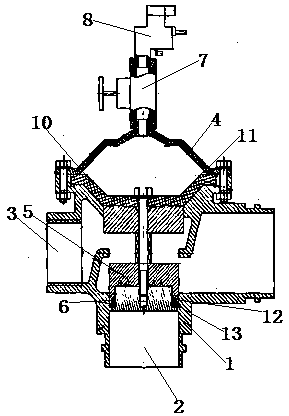
[0014] As shown in FIG. 1, a solenoid valve includes a valve body 1 made of aluminum alloy material. The valve body 1 is provided with a water inlet 2 and a water outlet 3, and also includes a valve cover 4, a valve disc 5, a sealing assembly 6, Two-way constant flow valve 7, pilot valve 8, valve stem 9, diaphragm 10, diaphragm 10 is a water-sealing diaphragm, the diaphragm 10 is located between the valve body 1 and the valve cover 4, the valve stem 9 and the The valve flap 5 is located under the diaphragm 10, and on the two sides of the valve flap 5, a plurality of circular grooves 11 are arranged on one side near the diaphragm 10, and the side near the water inlet 3 is set as a conical surface to seal The component 6 is a sealing ring 12 and a retaining ring 13, wherein the retaining ring can play the role of guiding and preventing damage.

[0015] The working princ...


PUM


Abstract

The invention discloses a magnetic valve. The magnetic valve comprises a valve body, wherein a water inlet and a water outlet are formed inside the valve body. The magnetic valve also comprises a valve cover, a valve clack, a sealing assembly, a permanent flow valve, a guiding valve, a valve rod and a separation film; the separation film is arranged between the valve body and the valve cover; the valve rod and the valve clack are arranged below the separation film; one side of the valve clack, which is close to the separation film, is provided with a groove; one side of the valve clack, which is close to the water inlet, is a conical surface. The magnetic valve has the advantages of being simple in structure, effectively reducing water attack and being good in sealing effect.

Description

technical field [0001] The invention relates to the technical field of valves, in particular to an electromagnetic valve. Background technique [0002] Solenoid valves are very prone to water hammer during operation, but the existing solenoid valves cannot effectively reduce water hammer, and the sealing effect is not good and it is easy to leak. Contents of the invention [0003] In order to solve the above technical problems, the present invention provides a solenoid valve with simple structure, which can effectively reduce water hammer and has good sealing effect. [0004] The technical solution adopted in the present invention is: a solenoid valve, characterized in that it includes a valve body, the valve body is provided with a water inlet and a water outlet, and also includes a valve cover, a valve disc, a sealing assembly, a constant flow valve, and a pilot valve. , valve stem, and diaphragm, the diaphragm is located between the valve body and the valve cover, the ...

Claims


Application Information

Patent Timeline
IPC IPC(8): F16K1/00F16K47/02
CPCF16K31/0655F16K27/02F16K47/02
Inventor 罗宇新
Owner SUZHOU GUJI ELECTRONICS TECH
Why Eureka
Try Eureka