LED substrate for LED light bar and LED light bar with large light emitting angle

A technology of LED strips and LED substrates, which is applied in the direction of semiconductor devices, light sources, electric light sources, etc. of light-emitting elements, which can solve problems such as poor ductility and toughness, poor heat dissipation performance, and complicated processes, and achieve the effect of reducing restrictions

Inactive Publication Date: 2014-10-01
MLS
View PDF12 Cites 14 Cited by
  • Summary
  • Abstract
  • Description
  • Claims
  • Application Information

AI Technical Summary

Problems solved by technology

Although the replacement of non-transparent substrates with transparent substrates can expand the luminous angle, since transparent substrates are generally made of glass, ceramics or PC materials, compared with traditional non-transparent materials such as metals, transparent substrates have many problems: (1) Ductility and The toughness is poor, and it is easy to break during production and use, especially in the small-sized long strip structure (wick); (2) The heat dissipation performance is poor. In the LED lamp group, the LED crystal will generate a large amount of Heat, the heat needs to be conducted outward through the substrate, and glass, ceramics or PC materials have poor thermal conductivity, it is difficult to effectively export the heat generated by the LED crystal, and it is easy to cause the LED crystal temperature to rise rapidly and be damaged; (3) The process is complex , because glass, ceramics or PC materials themselves do not have conductivity, it is necessary to set multiple electroplating on the substrate to manufacture electrodes and conductive lines, resulting in complicated processes

Method used


Image

  • LED substrate for LED light bar and LED light bar with large light emitting angle
  • LED substrate for LED light bar and LED light bar with large light emitting angle
  • LED substrate for LED light bar and LED light bar with large light emitting angle

Examples


Embodiment 1

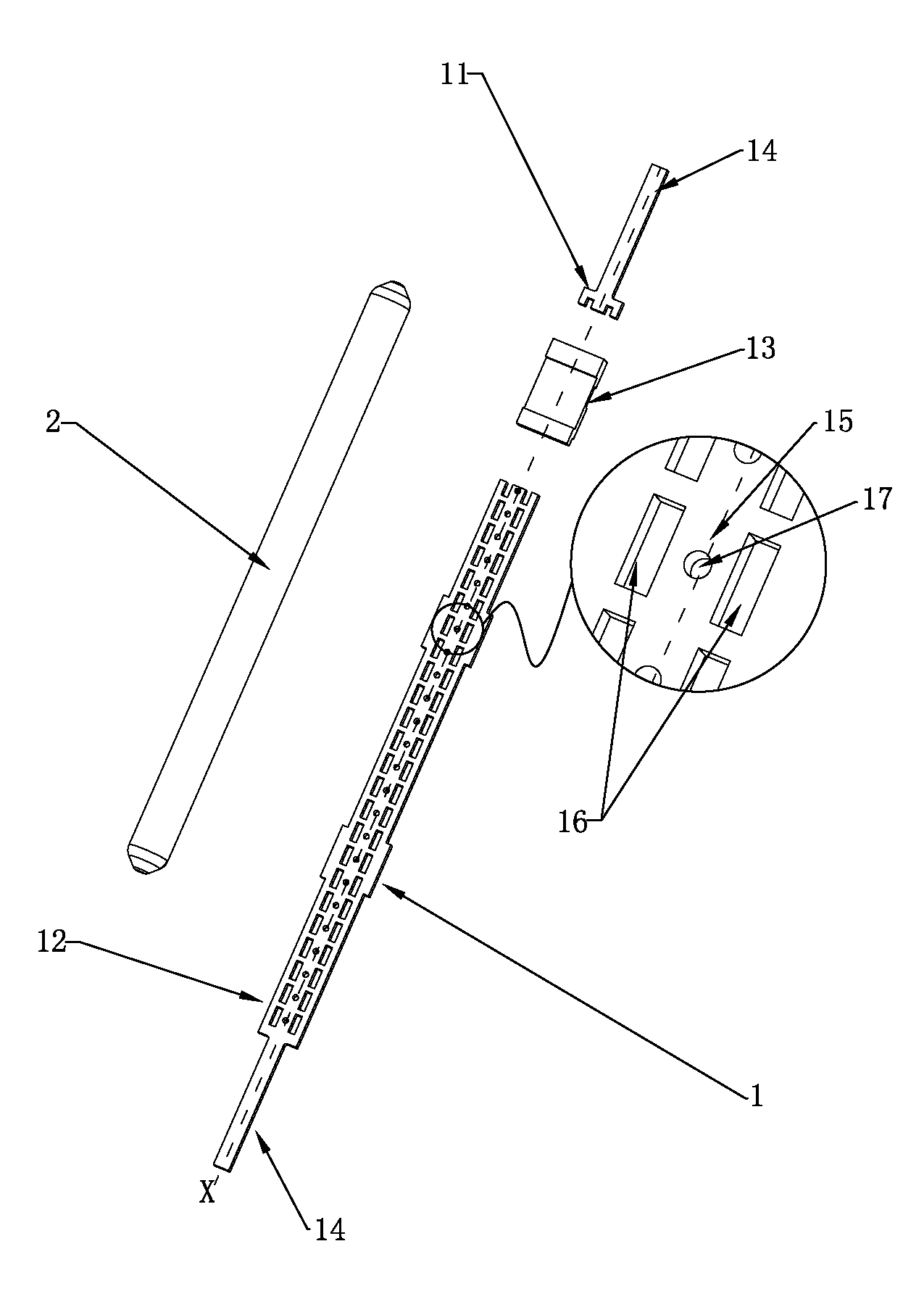
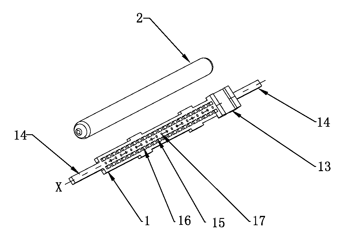
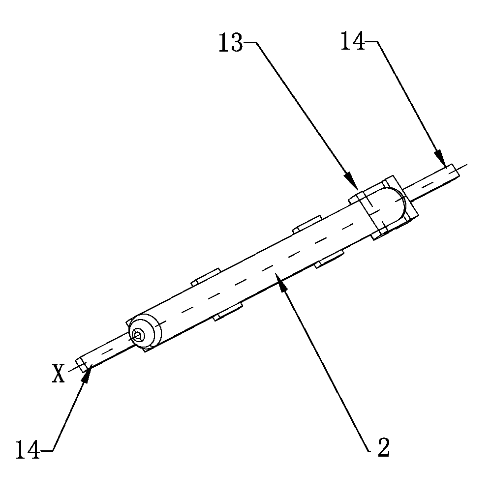
[0026] One of the specific implementation modes of the present application, such as Figure 1 to Figure 4 As shown, this embodiment takes a wick tube product used to form an LED wick column (see background art) as an example, which is composed of an LED substrate 1 , an LED crystal 3 , a fixing glue 4 and a fluorescent tube 2 .

[0027] The LED substrate 1 is in the shape of a strip, including a positive electrode copper sheet 11, a negative electrode copper sheet 12 and an insulating block 13. The positive electrode copper sheet 11 and the negative electrode copper sheet 12 are connected to the insulating block 13 respectively, so that the positive electrode copper sheet 11 and the negative electrode copper sheet 12 Structurally connected but electrically insulated, that is, the positive copper sheet 11 and the negative electrode copper sheet 12 are equivalent to the first electrode and the second electrode of the LED substrate 1 . Both the positive copper sheet 11 and the ne...

Embodiment 2

[0036] In the second embodiment of the present application, the main technical solutions of this embodiment are the same as those of Embodiment 1, and the features not explained in this embodiment are explained in Embodiment 1, and will not be repeated here. The difference between this embodiment and Embodiment 1 lies in that the crystal-bonding sites 15 on the front side and the crystal-bonding sites 15 on the back side of the crystal-bonding area are arranged in dislocation. In other words, odd-numbered crystal-bonding positions 15 such as 1, 3, and 5 fix the LED crystal 3 on the front of the LED substrate 1, and even-numbered crystal-bonding positions 15 such as 2, 4, and 8 fix the LED crystal 3 on the LED substrate 1. the opposite of . In this way, the purpose of more uniform light emission on both sides of the LED substrate 1 can be achieved.


PUM


Abstract

The invention provides an LED substrate and an LED light bar using the LED substrate. Light-pervious holes are formed in the side face of each crystal fixing position of the LED substrate, when encapsulation is carried out, LED crystals are fixed to the crystal fixing positions, fixing glue is applied on the crystal fixing positions in a point injection mode at the same time, and the light-pervious holes are filled with the fixing glue. Due to the fact that light rays emitted by the LED crystals pass through the fixing glue first and are then emitted into air, part of the light rays can be refracted at the interface of the fixing glue and the air and then directly emitted into the air, part of the light rays are reflected back into the fixing glue, are transmitted to the other side of the substrate through the light-pervious holes and are emitted from the other side of the substrate, restriction of the substrate on the light rays emitted by the LED crystals is reduced greatly, even if the substrate is made of nontransparent materials, the light rays emitted by the LED crystals can be emitted through the substrate, and light emitting by 360 degrees is achieved.

Description

technical field [0001] The present application relates to the technical field of LED packaging, in particular to an LED substrate used for an LED light bar and an LED light bar with a large luminous angle. Background technique [0002] With the development of electronic semiconductor technology, more and more lighting occasions use LED lamps to replace traditional lighting lamps. Due to the variety of lighting occasions, the structure of LED lamps is also varied. However, the basic structure is to fix and package the LED crystal on the substrate, and supply power to the LED crystal through the substrate to make the LED crystal emit light to realize lighting. The direct problem brought by this structure is that the light emitted by the LED crystal will be limited by the substrate, and the light emitting angle is small. However, in many lighting occasions, the light-emitting elements are required to have a larger luminous angle, or even 360-degree luminescence. For example,...

Claims


Application Information

Patent Timeline
Patent Type & Authority Applications(China)
IPC IPC(8): F21S4/00F21V23/06F21V19/00F21Y101/02F21S4/28F21Y115/10
Inventor 刘天明叶才
Owner MLS
Why Eureka
Try Eureka