Lever used in leveraged adjustable load dynamic test bench

A lever-type, test-bed technology, which is used in the testing of machines/structural components, measuring devices, instruments, etc., can solve the problem that ordinary levers cannot meet the test needs of test-beds, etc., and achieves easy realization of automated assembly lines, low cost and land occupation. less effect

Inactive Publication Date: 2014-10-01
北京起重工具厂
View PDF0 Cites 4 Cited by
  • Summary
  • Abstract
  • Description
  • Claims
  • Application Information

AI Technical Summary

Problems solved by technology

Traditional ordinary leverage structure such as figure 1 As shown, the ordinary lever 13 is a fixed structure, and the ordinary lever 13 has no holes on the side of the force arm and the side of the heavy arm. Meeting the test requirements of various actual wor

Method used


Image

  • Lever used in leveraged adjustable load dynamic test bench
  • Lever used in leveraged adjustable load dynamic test bench
  • Lever used in leveraged adjustable load dynamic test bench

Examples


Embodiment 1

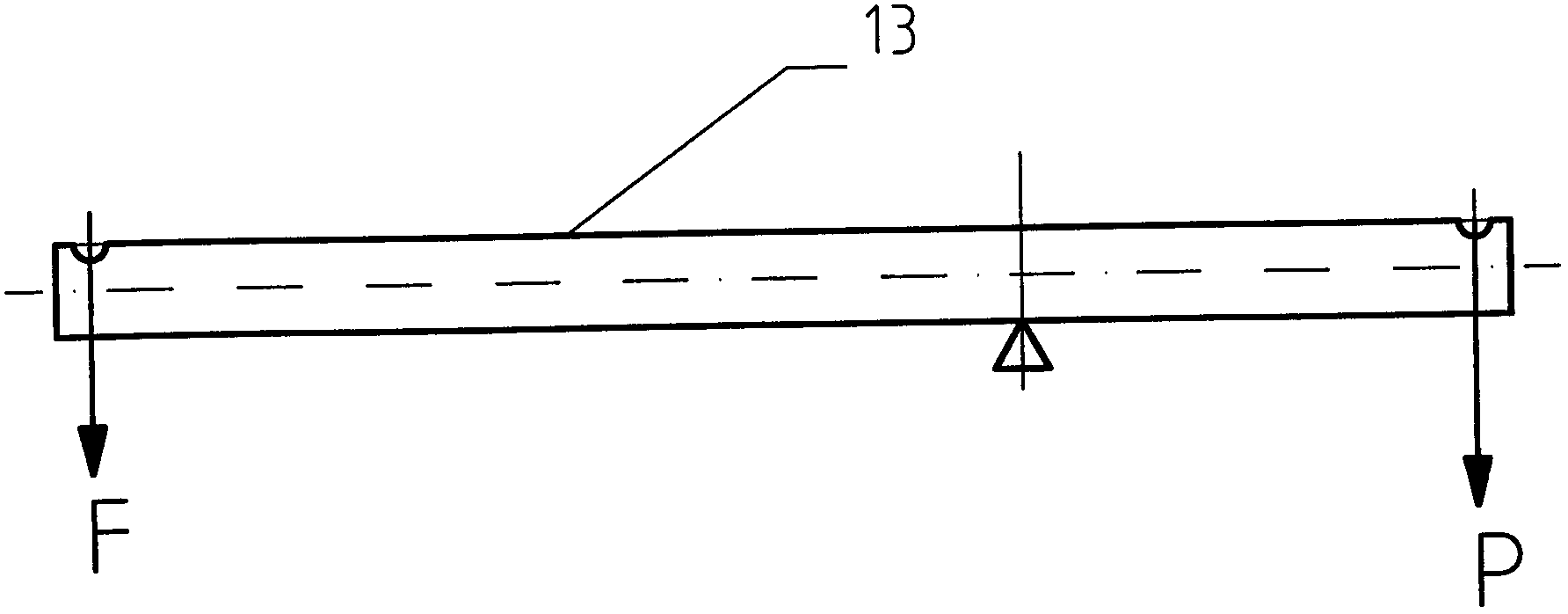
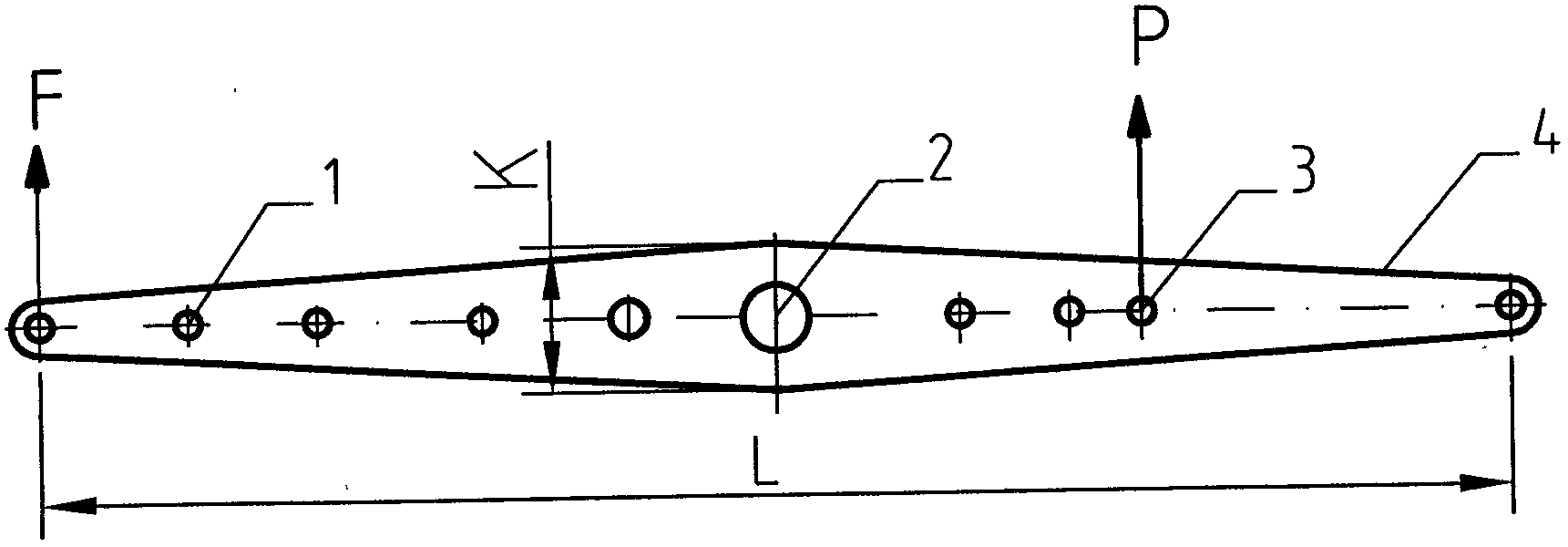
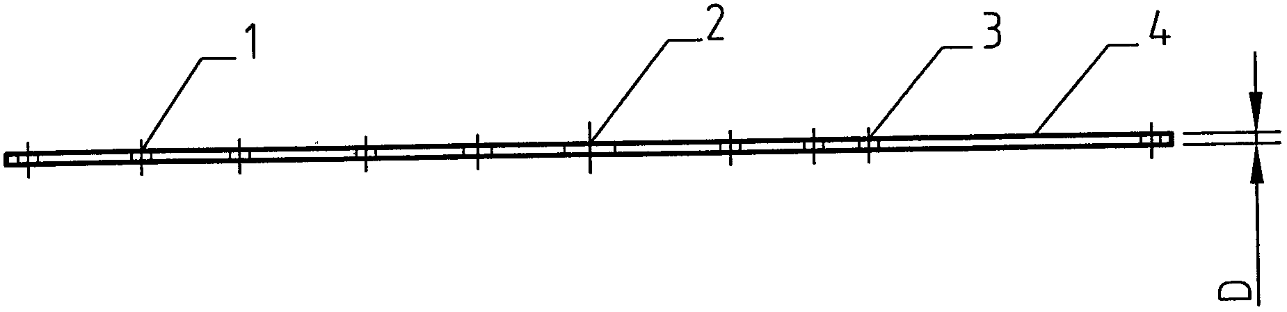
[0033] A lever used on a lever-type adjustable load dynamic load test bench, such as figure 2 , 3 Shown, on lever 4 force arm side, have force arm side mounting hole 1, force arm side mounting hole 1 can be one, or two, or three, or more (present embodiment force arm side mounting hole 1 is Five), the mounting holes 1 on the arm side can be arranged in any position on the arm side in sequence;

[0034] On the lever 4 heavy arm side, there are heavy arm side mounting holes 3, and the heavy arm side mounting holes 3 can be one, or two, or three, or more (the present embodiment heavy arm side mounting holes 3 are four ), the mounting holes 3 on the boom side can be arranged in sequence at any position on the boom side;

[0035] There is a lever support point hole 2 between the lever 4 arm side and the lever 4 heavy arm side;

[0036] The material of the lever 4 is a material whose strength is greater than or equal to the strength of steel, which can be steel;

[0037] The le...

Embodiment 2

[0059] A kind of lever used on the lever-type adjustable load dynamic load test bench, its structure is basically the same as that of embodiment 1, the only difference is as follows Figure 4 As shown, there is a horizontal rail groove 5 on the arm side of the lever 4, and the mounting hole 1 on the arm side is opened in the horizontal rail groove 5, and the fixed shaft installed in the mounting hole 1 on the arm side can Exit downward and move along the horizontal track groove 5 to the other arm side mounting hole 1 for fixation.

Embodiment 3

[0061] A kind of lever used on the lever-type adjustable load dynamic load test bench, its structure is basically the same as that of embodiment 1, the only difference is as follows Figure 5 As shown, there is a horizontal rail groove 5 on the heavy arm side of the lever 4, and the mounting hole 3 on the heavy arm side is opened in the horizontal rail groove 5, and the fixed shaft installed in the mounting hole 3 on the heavy arm side can be moved from the The lower exit moves along the horizontal track groove 5 and is fixed in the mounting hole 3 on the other boom side.


PUM

PropertyMeasurementUnit
Lengthaaaaaaaaaa
Widthaaaaaaaaaa
Thicknessaaaaaaaaaa

Abstract

The invention discloses a lever used in leveraged adjustable load dynamic test bench, belongingto the technical field of components on dynamic load testing equipment. A lever force arm side is provided with a force arm side mounting hole. A lever heavy arm side is provided with a heavy arm side mounting hole. A lever supporting point hole is opened between the lever force arm side and the lever heavy arm side, and is assembled with other components into a complete load adjustable test bench, so that the test bench can solve the problem of a conventional test bench, and the lever is simple to process. The lever structure helps to achieve an adjustable leverage point and an adjustable gravity force applying position, and has the advantages that the force direction and the gravity force applied direction are upward, and the force applied on the upper surface of the support point is downward.

Description

technical field [0001] The invention discloses a lever used on a lever-type adjustable load dynamic load test bench, which belongs to the component of the test equipment in the technical field of dynamic load detection, in particular to a lever-type adjustable load dynamic load used for chain hoist detection on the test bench. Background technique [0002] At present, the quality and safety testing and inspection of products in the lifting field adopts the dynamic load test or type test of the tested product (test piece). These two test methods usually adopt the direct weight method that simulates the actual working conditions (and in a few cases, the hydraulic loading method is used). The test bench used by the direct weight method has a series of problems such as large area, high cost, many weights, laborious adjustment, low efficiency, and poor connection with final assembly and packaging inspection; in a few cases, it is used The test bench used in the hydraulic loadin...

Claims


Application Information

Patent Timeline
IPC IPC(8): G01M99/00
Inventor 李鉴根王军
Owner 北京起重工具厂
Why Eureka
Try Eureka