Combined electromagnetic cloaking device

A combined, electromagnetic technology, applied in the electromagnetic field, can solve problems affecting device size miniaturization, waste of materials and costs, and occupancy

Active Publication Date: 2014-10-01
XIDIAN UNIV
View PDF1 Cites 14 Cited by
  • Summary
  • Abstract
  • Description
  • Claims
  • Application Information

AI Technical Summary

Problems solved by technology

However, the invisibility of this cylindrical complementary medium invisibility cloak is not directional. In the case of cloaking a directional target object, only a small area of ​​this cloak plays a role, while most of

Method used


Image

  • Combined electromagnetic cloaking device
  • Combined electromagnetic cloaking device
  • Combined electromagnetic cloaking device

Examples


Embodiment Construction

[0082] The electromagnetic cloaking device designed by the present invention limits the wavelength corresponding to the operating frequency required for the cloaking effect to be similar to the geometric size of the cloaking device of the present invention.

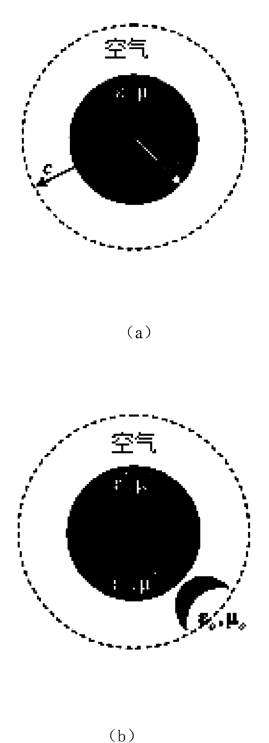
[0083] The combined electromagnetic stealth device designed by the present invention has a stealth effect for electromagnetic waves incident in any direction perpendicular to the cylindrical axis; compared with the traditional cylindrical stealth device, the electromagnetic stealth device designed by the present invention can be invisible The target object in the direction is directional.

[0084] The material parameters of the object include dielectric constant ε and magnetic permeability μ, and the electromagnetic device designed in the present invention is made of anisotropic metamaterial; A near-rectangular cylinder with a circular arc on one side, with the same material parameters along the axis;

[0085] The combin...


PUM


Abstract

The invention relates to the technical field of electromagnetics, and specifically discloses an external electromagnetic cloaking device designed by using a boundary splicing technology. The electromagnetic cloaking device comprises a fan-shaped post which is cut from a cylindrical complementary media invisible cloak and consists of a 1b core region and a 2b complementary media region; the cross section of the fan-shaped post is a sector with an included angle of 2theta; the bent cambered surface of the fan-shaped post is a portion of the side face of the cylindrical complementary media invisible cloak. The electromagnetic cloaking device consists of a 1a core region, a 1b core region, a 1c core region, a 2a complementary media region, a 2b complementary media region and a 2c complementary media region. An external invisible cloak of any shape can be cut by adopting the boundary splicing technology, and the disclosed combined electromagnetic cloaking device is constructed by splicing other regions on the boundary of a section. By adopting the electromagnetic cloaking device, the size of the cloaking device can be reduced greatly, and the cost and space are saved. A method for designing the combined electromagnetic cloaking device can be applied to the design of any other external electromagnetic cloaking device.

Description

technical field [0001] The invention relates to the field of electromagnetic technology, in particular to a combined electromagnetic cloaking device. Background technique [0002] In 1968, the former Soviet physicist V.G. Veselago proposed for the first time that when the permittivity ε and magnetic permeability μ are both negative, the electric field, magnetic field and wave vector will form a left-handed relationship. Since this medium is not found in nature, his research results have not been experimentally verified in the last century, let alone in-depth research. In 1996, J.B.Pendry et al. designed and implemented a periodic arrangement of metal thin wires (Rod) array structure with negative equivalent dielectric constant in the microwave frequency band; in 1999, Pendry et al. proposed the use of open loop resonators (SRRs: Split Ring Resonators) to realize the medium whose equivalent permeability is negative. In 2000, according to Pendry's theoretical model, D.R.Smit...

Claims


Application Information

Patent Timeline
IPC IPC(8): G06F3/01
Inventor 史琰唐薇
Owner XIDIAN UNIV
Why Eureka
Try Eureka