Voltage source type direct-current deicing and static synchronous compensation device and control method thereof

A static synchronous compensation, DC ice melting technology, applied in the installation of cables, reactive power adjustment/elimination/compensation, electrical components, etc.

Active Publication Date: 2014-10-01
ELECTRIC POWER RESEARCH INSTITUTE, CHINA SOUTHERN POWER GRID CO LTD
View PDF5 Cites 29 Cited by
  • Summary
  • Abstract
  • Description
  • Claims
  • Application Information

AI Technical Summary

Problems solved by technology

[0009] The purpose of the present invention is to overcome the shortcomings of the existing thyristor DC ice melting device and provide a voltage source type DC ice melting and static synchronous compensation device that can meet the ice melting needs of transmission lines of various voltage levels

Method used


Image

  • Voltage source type direct-current deicing and static synchronous compensation device and control method thereof
  • Voltage source type direct-current deicing and static synchronous compensation device and control method thereof
  • Voltage source type direct-current deicing and static synchronous compensation device and control method thereof

Examples


Embodiment 1

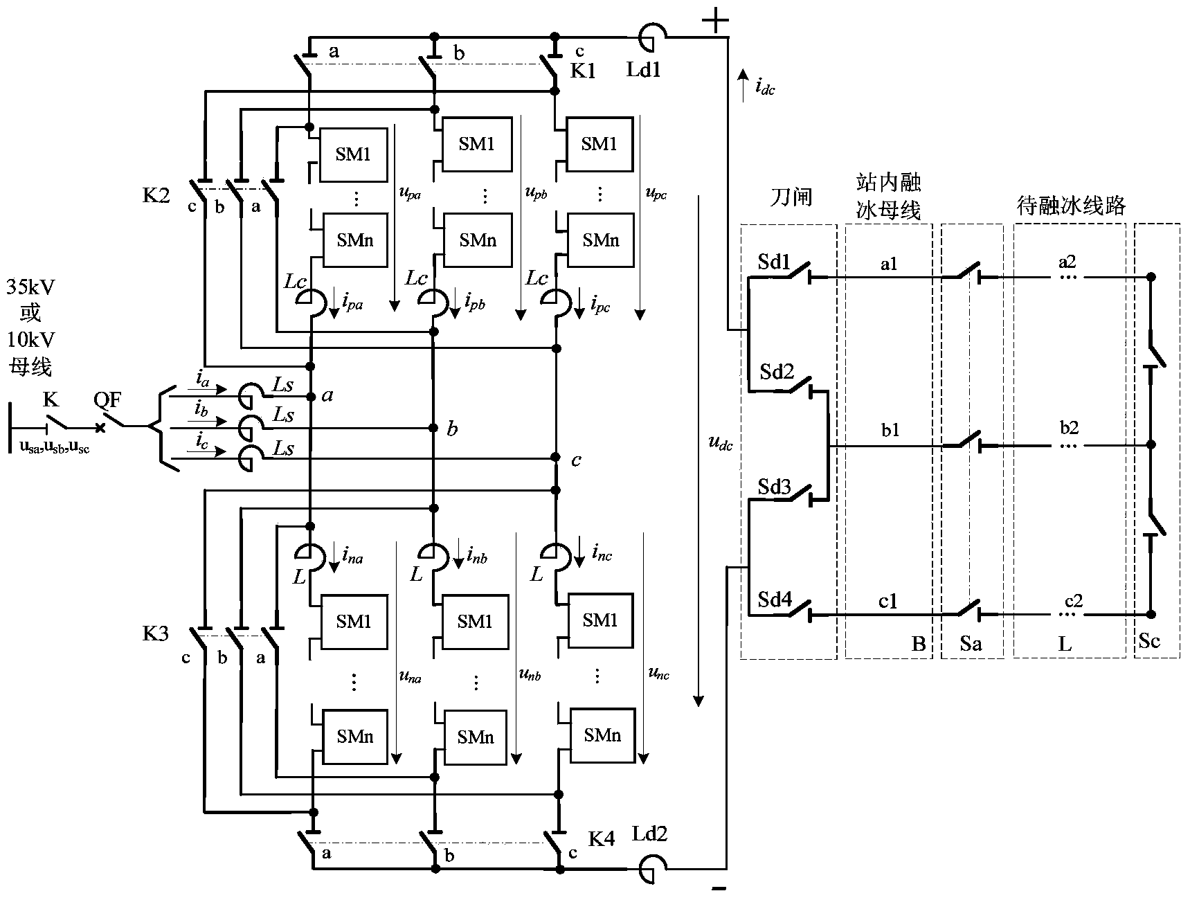
[0059] The structural diagram of the voltage source type DC ice melting and static synchronous compensation device of the present invention is as follows figure 1 As shown, the voltage source type DC ice-melting and static synchronous compensation device of the present invention includes at least one basic commutation unit, the basic commutation unit includes an isolation switch K, a circuit breaker QF, and a connecting reactor Ls. The modular multilevel converter MMC of the bridge sub-module, the knife gates K1, K2, K3, K4, smoothing reactors Ld1, Ld2; among them, the modular multilevel converter MMC, the connecting reactor Ls and the knife gate K1, K2, K3, and K4 all include three phases a, b, and c, and the three-phase structures are exactly the same; one end connected to the reactor Ls is connected to the AC side bus through the isolation switch K and the circuit breaker QF, and the other end It is connected to the corresponding phases of the AC input terminals of the modu...

Embodiment 2

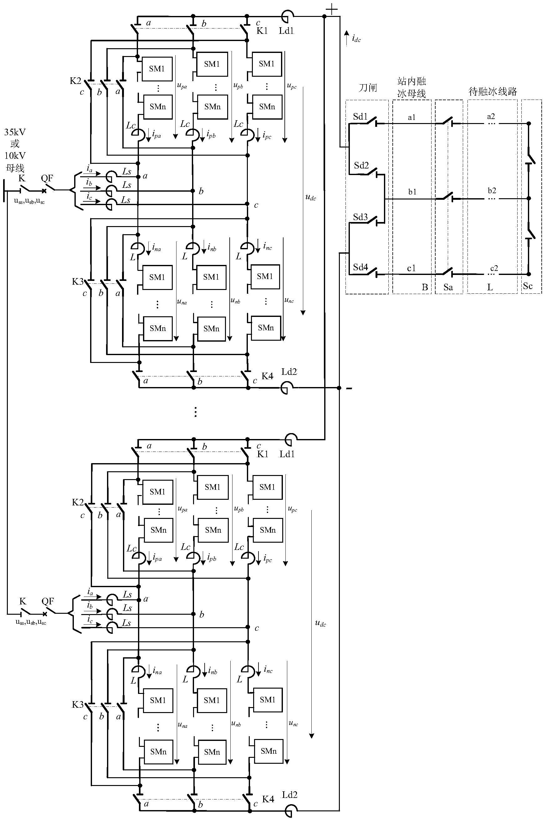
[0100] The structural diagram of the voltage source type DC ice melting and static synchronous compensation device of the present invention is as follows figure 2 As shown, there are M basic converter units, where M is a positive integer; one end of the smoothing reactor Ld1 of the M basic converter units is connected together, and one end of the smoothing reactor Ld2 of the M basic converter units connected together, one end of the switch Sd1, Sd2 is connected to the other end of the smoothing reactor Ld1 of the M basic converter units, and one end of the switch Sd3, Sd4 is connected to the smoothing reactor Ld1 of the M basic converter units. The other end of the reactor Ld2 is connected, the other end of the knife switch Sd1 is connected to one end of the a1 phase of the ice-melting bus B in the station, and the other end of the knife switch Sd2 and Sd3 is connected to one end of the b1 phase of the ice-melting bus B in the station. The other end of the knife switch Sd4 is...

Embodiment 3

[0104] The structure of the voltage source type DC ice-melting and static synchronous compensation device of the present invention is the same as that of embodiment 1 or embodiment 2, wherein the full-bridge sub-module in the modular multi-level converter MMC adopts a single fully-controlled device Full-bridge sub-module, the structural diagram of the full-bridge sub-module using a single full-control device is shown in Figure 5 As shown, it includes four fully controlled devices S1, S2, S3, S4, four diodes D1, D2, D3, D4, a capacitor C, a thyristor SCR, a fast switch Ks, fully controlled device S1 and diode D1 Anti-parallel connection, fully-controlled device S2 is connected in reverse parallel with diode D2, fully-controlled device S3 is connected in reverse parallel with diode D3, fully-controlled device S4 is connected in reverse parallel with diode D4, that is, the positive terminal of the fully-controlled device is connected to the diode negative The negative terminal o...


PUM


Abstract

The invention discloses a voltage source type direct-current deicing and static synchronous compensation device and a control method thereof. The voltage source type direct-current deicing and static synchronous compensation device comprises at least one basic current convertor unit. The basic current convertor unit comprises a connection electric reactor Ls, a modular multi-level current convertor MMC adopting a full-bridge sub-module, disconnecting links (K1, K2, K3 and K4), and smoothing electric reactors (Ld1 and Ld2). The voltage source type direct-current deicing and static reactive generation device can meet the requirements for deicing of power transmission lines of various voltage classes. The method for switching the voltage source type direct-current deicing and static synchronous compensation device among different function modes and the control method of the voltage source type direct-current deicing device can meet the requirement for safe and rapid deicing of the lines, no harmonic pollution at an access point is caused, and dynamic reactive power compensation can be provided for the access point. The voltage source type direct-current deicing and static synchronous compensation device can be used for a newly-constructed direct-current deicing project, can also be used for upgrading and reconstruction of the direct-current deicing device in the constructed direct-current deicing project, and has the wide application prospect.

Description

technical field [0001] The invention relates to a voltage source type DC deicing and static synchronous compensation device and its control method, in particular to a DC deicing and static synchronous compensation device based on a full-bridge sub-module modular multilevel converter and its The control method relates to the technical fields of high-power power electronics and power transmission line melting ice. Background technique [0002] Among the various natural disasters suffered by the power system, ice disaster is one of the most serious threats. With the continuous improvement of the level of modernization, the whole society relies more and more on electricity, which also puts forward higher requirements for electricity supply. In recent years, various meteorological disasters around the world have become more frequent, extreme weather and climate events have become more abnormal, ice disasters have caused more serious losses and impacts on the power system, and th...

Claims


Application Information

Patent Timeline
Patent Type & Authority Applications(China)
IPC IPC(8): H02G7/16H02J3/18
CPCH02G7/16Y02E40/10
Inventor 傅闯饶宏
Owner ELECTRIC POWER RESEARCH INSTITUTE, CHINA SOUTHERN POWER GRID CO LTD
Why Eureka
Try Eureka