Solar cell unit and solar cell module

A technology of solar cells and components, applied in electrical components, circuits, photovoltaic power generation, etc., can solve problems such as unsuitable safety and cost, daily inspection, complicated operations, etc., and achieve the effects of ensuring power generation capacity, improving reliability, and suppressing damage

Inactive Publication Date: 2014-10-01
JX NIPPON OIL & ENERGY CORP
View PDF4 Cites 7 Cited by
  • Summary
  • Abstract
  • Description
  • Claims
  • Application Information

AI Technical Summary

Problems solved by technology

[0006] However, in the above-mentioned technology, as described above, in order to detect the open mode failure of the bypass diode, it is necessary to shield the solar cell from light, but the solar cell unit is usually installed on a high place such as a roof, so there is a problem that the work Realistically cumbersome and unsuitable for routine inspection from the standpoint of safety and cost

Method used


Image

  • Solar cell unit and solar cell module
  • Solar cell unit and solar cell module
  • Solar cell unit and solar cell module

Examples


no. 1 approach

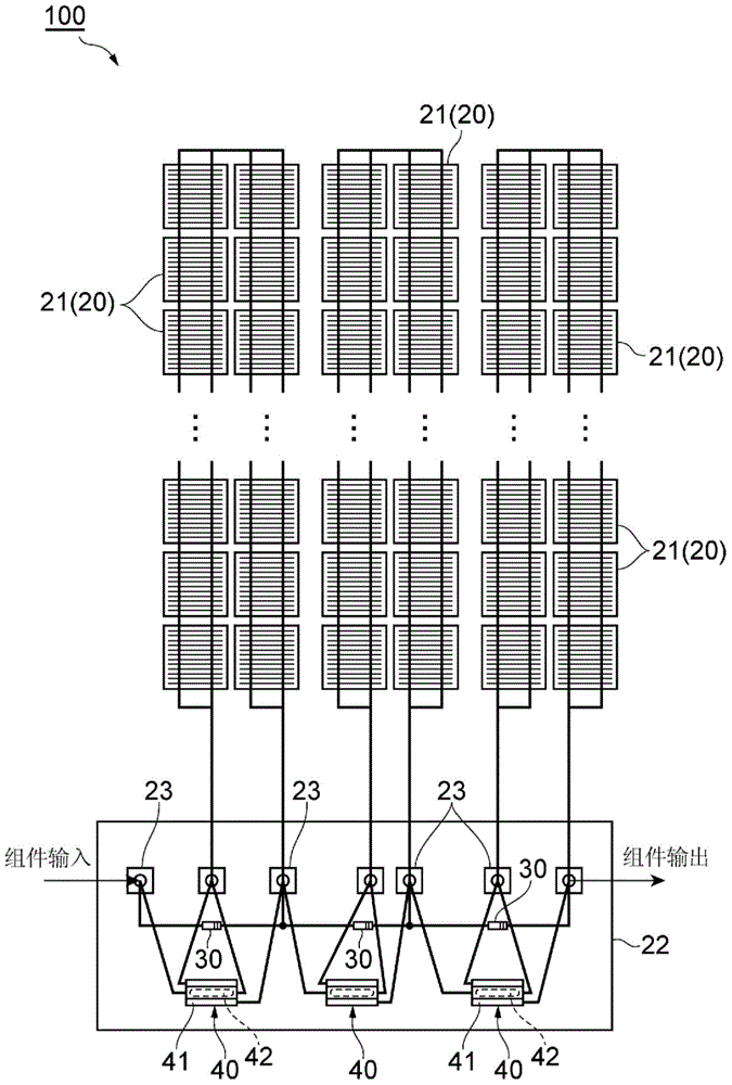
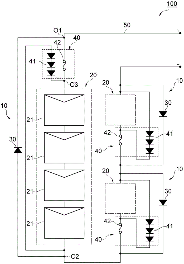
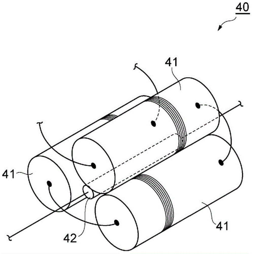
[0035] The first embodiment will be described. figure 1 is a configuration diagram showing the solar cell module according to the first embodiment, figure 2 yes figure 1 A schematic circuit diagram of a solar module, image 3 It is a perspective view showing an element complex. Such as figure 1 , 2 As shown, a plurality of solar cell modules 100 of this embodiment are installed in series on a high place such as a roof, for example, to constitute a system-cooperative photovoltaic power generation system having an output voltage of 200V or higher. The solar cell module 100 includes a plurality of (here, three) solar cell cells 10 connected in series.

[0036]Each of the plurality of solar cells 10 is configured to include a solar cell cluster (solar cell) 20 , a bypass diode 30 , and an element complex 40 . The solar cell cluster 20 includes a plurality of solar cell cells 21 connected in series, and generates electricity using sunlight. The plurality of solar battery...

no. 2 approach

[0063] Next, a second embodiment will be described. In addition, in the description of this embodiment, differences from the first embodiment described above will be mainly described.

[0064] Figure 6 is a configuration diagram showing a solar cell module according to the second embodiment, Figure 7 yes Figure 6 A schematic circuit diagram of a solar module. Such as Figure 6 and Figure 7 As shown, the solar cell module 200 of this embodiment is the same as the above-mentioned solar cell module 100 (refer to figure 1 and figure 2 ) differ in that the circuit structures of the bypass diode 30 and the element complex 40 are changed. That is, in figure 1 and figure 2 In the solar cell module 100 shown, the bypass diode 30 is connected in parallel to the solar cell clusters 20 connected in series and the thermal fuse 42, while in the solar cell module 200 of the second embodiment, as Figure 6 and Figure 7 As shown, the bypass diode 30 is connected in parallel...

no. 3 approach

[0069] Next, a third embodiment will be described. In addition, in the description of this embodiment, differences from the second embodiment described above will be mainly described.

[0070] Figure 8 It is a schematic circuit diagram showing the solar cell module according to the third embodiment. Such as Figure 8 As shown, the solar cell module 300 of this embodiment is the same as the above-mentioned solar cell module 200 (refer to Figure 7 ) is different in that a thermal fuse 342 common to a plurality of solar battery cells 10 is provided instead of a plurality of thermal fuses 42 provided for each of the plurality of solar battery cells 10 .

[0071] The thermal fuse 342 is connected in series to the plurality of solar cell clusters 20 and the plurality of bypass diodes 30 . The thermal fuse 342 cuts off the connection with the plurality of solar battery cells 10 according to the heat generated by at least one of the plurality of heat generating diodes 41 , and c...


PUM


Abstract

This solar cell unit is provided with solar cells, which generate power using solar light, and bypass diodes, which are connected in parallel to the solar cells. The solar cell unit is also provided with reactive elements, which are connected in parallel to the solar cells and the bypass diodes, and which react when a current flows, and blocking elements, which are connected in series to the solar cells. The reactive elements are configured to have a current flow and to react, in the cases where a reverse voltage is applied to the solar cells and a current is not flowing to the bypass diodes. The blocking elements block, corresponding to the reactions of the reactive elements, the current flowing in the solar cells.

Description

technical field [0001] The invention relates to a solar cell unit and a solar cell assembly. Background technique [0002] Generally, in a solar cell unit that generates electricity using sunlight, a reverse voltage may be applied to the solar cell due to, for example, a variation in characteristics or a change in the intensity of sunlight. When the reverse voltage becomes high, the solar cell may be damaged. heat, or even breakage. Therefore, as a conventional solar cell, a solar cell is known in which a bypass diode is connected in parallel to the solar cell to suppress an excessive reverse voltage from being applied to the solar cell. [0003] In such a solar battery cell, for example, as described in Patent Document 1 below, a technique for detecting an open mode (open mode, also referred to as an open mode) failure of a bypass diode has been developed. In the inspection device described in Patent Document 1, the solar cell is shielded from light by a shielding plate, ...

Claims


Application Information

Patent Timeline
Patent Type & Authority Applications(China)
IPC IPC(8): H01L31/02H02H7/20
CPCH01L31/0504H02H7/20H01L31/02021H01L31/044H01L27/1421H02S40/34Y02B10/12Y02E10/50Y02B10/10
Inventor 吉富政宣石井隆文
Owner JX NIPPON OIL & ENERGY CORP
Why Eureka
Try Eureka