light miscellaneous separator

A separator and light impurity technology, which is applied in the direction of solid separation, separation of solids from solids by air flow, chemical instruments and methods, etc., can solve the problem of poor impurity removal effect, grain materials cannot be spread evenly, and cannot guarantee the quality of materials Flow balance and other issues to achieve the effect of low air consumption and long service life of equipment

Active Publication Date: 2015-12-30
河南友宸工程科技有限公司
View PDF6 Cites 0 Cited by
  • Summary
  • Abstract
  • Description
  • Claims
  • Application Information

AI Technical Summary

Problems solved by technology

Since the cleaning equipment is directly connected to the material conveying pipeline, the grain material cannot be spread evenly. Although the structure of the equipment is not complicated, the cleaning effect is not good
For example, the Chinese invention patent application (Application No. 201210088071.2, invention name "Suction Separator") discloses a suction separator used to separate the dust generated by the material during the flour production process after settling, and the grain enters through the pipeline during work. equipment, which cannot cleanly remove light impurities such as straws contained in grains; Chinese utility model patent (patent number 201320554103.3, invention name "A wear-resistant and anti-blocking suction separator") also discloses a grain particle impurity removal machine Equipment --- wear-resistant plugging suction separator, a cleaning device used to remove impurities such as straw in grains, although it can remove some impurities, but because only a pressure door is added at the entrance of the equipment to control the flow, it still cannot Ensure material flow balance

Method used


Image

  • light miscellaneous separator
  • light miscellaneous separator
  • light miscellaneous separator

Examples


Embodiment Construction

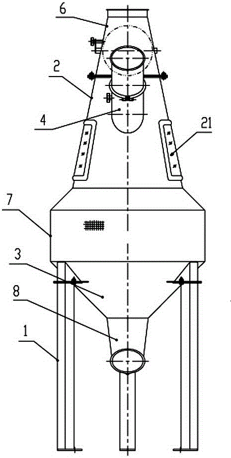
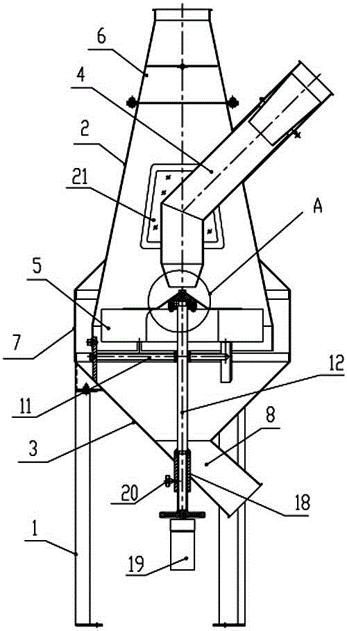
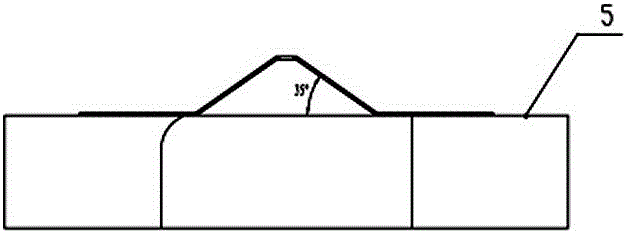
[0020] Such as figure 1 , 2 As shown, the light miscellaneous separator of the present invention includes a separation shell with a frame 1, and a feed inlet, a discharge port, an air inlet and a sundry collection port are opened on the separation shell, and the separation shell The body is composed of an upper chamber 2 and a lower chamber 3 connected by the inner cavity; the upper chamber 2 side wall of the positive conical cylinder structure is provided with a feeding port, and the feeding pipe 4 connected to the external feeding pipeline Extending from the feeding port into the upper chamber 2, a leveling pan 5 driven by a power source to rotate horizontally is provided near the bottom of the upper chamber, and the mouth of the feeding pipe 4 corresponds to the center of the leveling pan 5; An exhaust pipe 6 with an adjustable damper is connected to the mouth of the top of the upper chamber, and the exhaust pipe 6 is connected to the external centralized air network syste...


PUM


Abstract

The invention discloses a light impurity separator. The light impurity separator comprises a separating casing formed by combining an upper chamber and a lower chamber which are communicated through an inner cavity. A side wall of the upper chamber is provided with a feeding port, a feeding pipe extends into the upper chamber through the feeding port, a material uniformizing disc is arranged at the position close to the bottom of the upper chamber, a pipe opening of the feeding pipe corresponds to the center of the material uniformizing disc, the position of a drum opening at the top of the upper chamber is connected with an air draft pipe with an adjusting air door, the air draft pipe is connected with an external concentrated air net system, an air chamber is annularly arranged on the outer side of the upper chamber corresponding to the position of the material uniformizing disc, a side wall of the air chamber is provided with an air inlet, the lower chamber is of an inverted conical drum structure, and a discharging port located at the bottom of the lower chamber is communicated with an external material collecting device through a discharging pipe. The light impurity separator has the advantages that materials are evenly spread by utilizing the material uniformizing disc, mobility of the materials can be guaranteed, light impurities in the materials such as straw and chaff can be effectively removed, air volume consumption is low, the light impurity separator is long in service life, and working efficiency can be 1-2 tons / h.

Description

technical field [0001] The invention relates to grain processing equipment, in particular to a light impurity separator for removing stalks and husks in grains. Background technique [0002] At present, most of the cleaning equipment used by grain processing enterprises to remove straw and chaff light debris contained in grains are vertical suction ducts and circulating air suction separators. Since the cleaning equipment is directly connected to the material conveying pipeline, the grain material cannot be spread evenly. Although the structure of the equipment is not complicated, the cleaning effect is not good. For example, the Chinese invention patent application (Application No. 201210088071.2, invention name "Suction Separator") discloses a suction separator used to separate the dust generated by the material during the flour production process after settling, and the grain enters through the pipeline during work. equipment, which cannot cleanly remove light impurities...

Claims


Application Information

Patent Timeline
Patent Type & Authority Patents(China)
IPC IPC(8): B07B11/06B07B11/02
Inventor 杜秀玲李继侠陈高雅孙惠毕圣囡马传国杨磊
Owner 河南友宸工程科技有限公司
Why Eureka
Try Eureka