Road and railway power generation system

A technology of power generation system and railway, applied in the direction of engine, machine/engine, mechanical equipment, etc., can solve the problem of high investment, achieve the effect of low investment and easy construction and installation

Active Publication Date: 2014-10-08
临沂未来科技城开发建设集团有限公司
View PDF5 Cites 0 Cited by
  • Summary
  • Abstract
  • Description
  • Claims
  • Application Information

AI Technical Summary

Problems solved by technology

The above power generation modes are restricted by factors such as energy, high investment, natural environment and environmental protection.

Method used


Image

  • Road and railway power generation system
  • Road and railway power generation system
  • Road and railway power generation system

Examples


Embodiment Construction

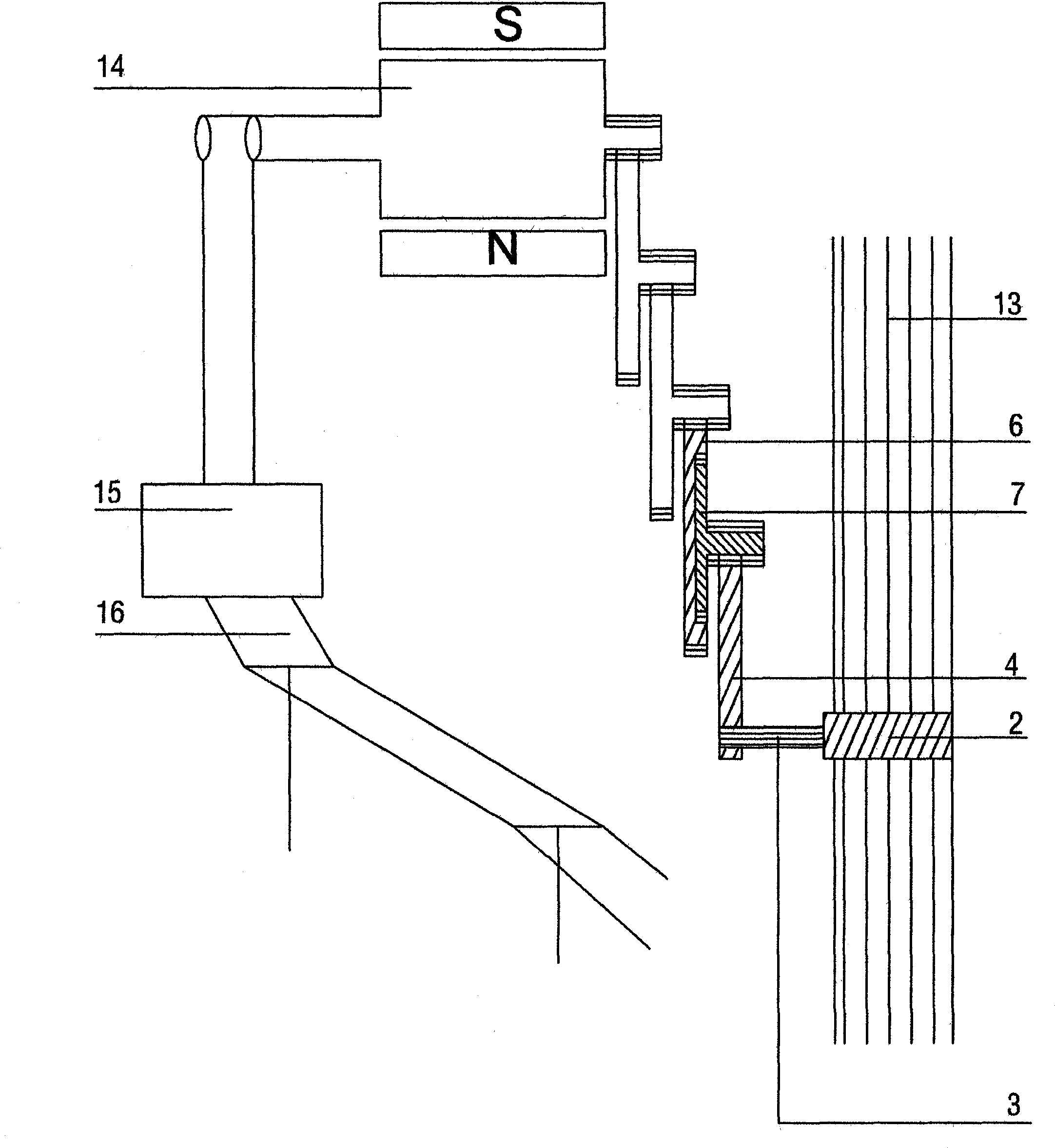
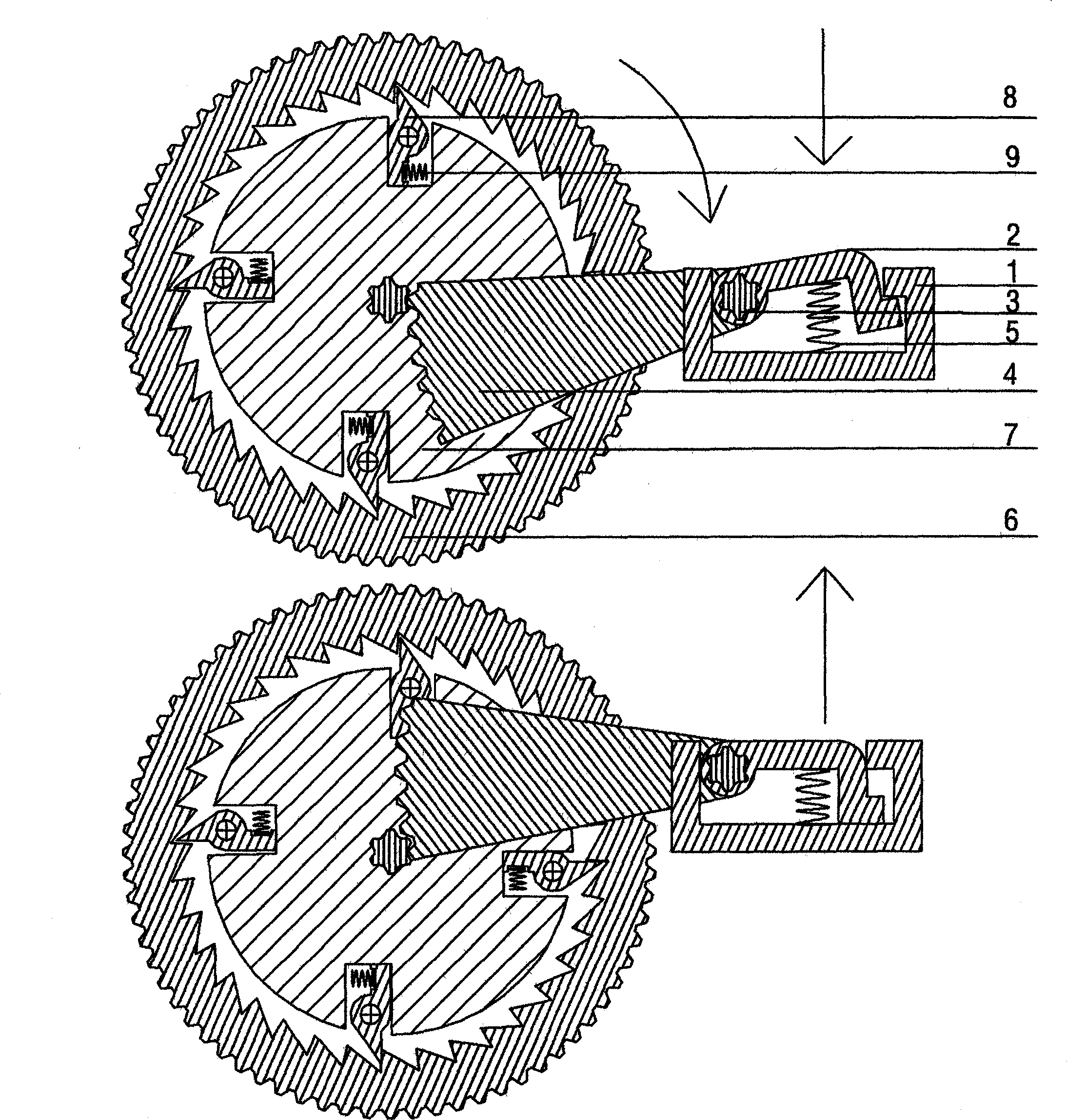
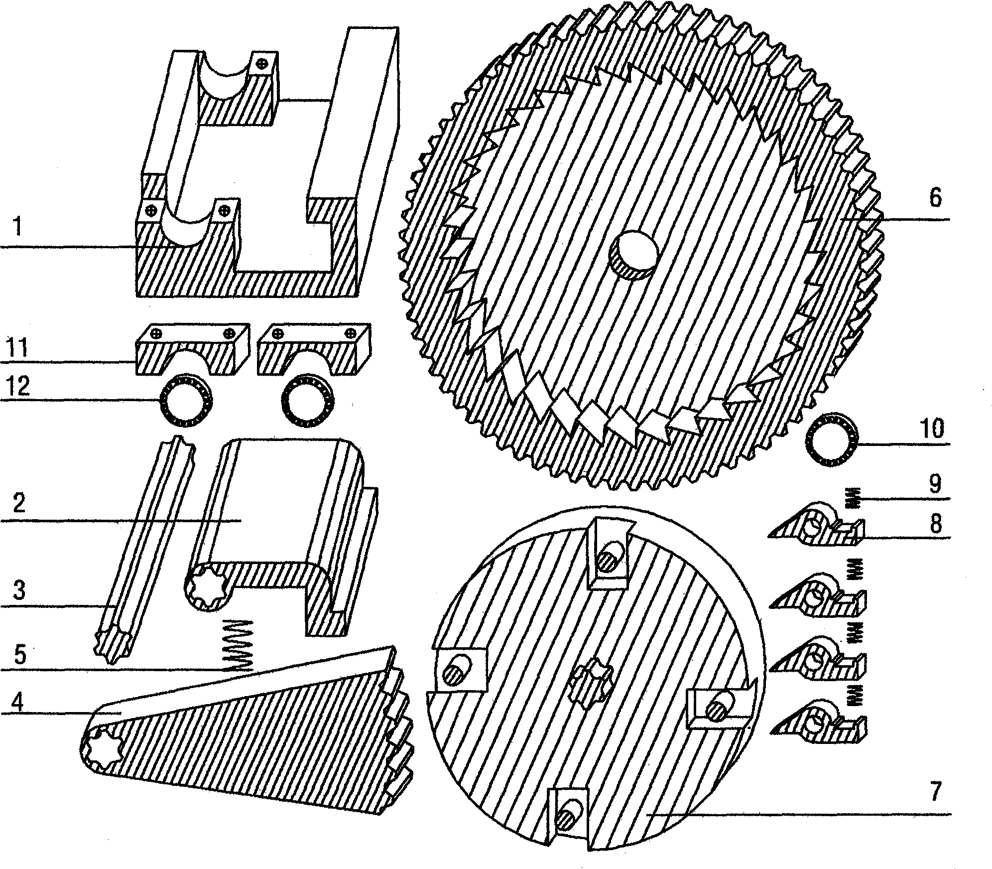
[0010] It can be seen from the accompanying drawings that the power generation system is composed of gravity converter, gravity conversion arm, one-way acceleration gear set, generator, voltage regulator, and transmission lines. (1. Since generators and voltage regulators are mature technologies, this article will not introduce them; 2. The only difference between the railway power generation system and the road power generation system is that the rails and the gravity conversion pedal in the railway power generation system are integrated. It is also not covered in this article). The power generation system includes a gravity conversion pedal housing 1 installed on roads or railways 13, a gravity conversion pedal 2 installed in the gravity conversion pedal housing 1, a gravity conversion pedal return spring 5 below the gravity conversion pedal 2, and a torsion shaft. 3 Connect the gravity conversion arm 4 through the gravity conversion pedal 2, the fan-shaped teeth of the grav...


PUM


Abstract

The invention relates to a power generation system which comprises a gravity convertor, a gravity conversion arm, a unidirectional acceleration gear set, a generator, a voltage regulator and a power transmission line and is characterized in that a gravity conversion pedal shell is mounted on a road or a railway; a gravity conversion pedal is mounted in the shell; a gravity conversion pedal returning spring is mounted under the gravity conversion pedal; a torsion shaft is connected with the gravity conversion pedal and the gravity conversion arm; sector teeth of the gravity conversion arm are meshed with gears of unidirectional drivers mounted in unidirectional reduction gears; unidirectional tooth blocks arranged on the unidirectional drivers are unidirectionally meshed with internal teeth of the unidirectional reduction gears under the action of unidirectional tooth block returning springs; the unidirectional reduction gear set is finally meshed with the generator; a power generation line of the generator is connected with the voltage regulator; the voltage regulator is connected with the power transmission line, so that the electric energy after being adjusted by the voltage regulator can be input to the national grid. The power generation system has the advantages of environment protection, low investment, easiness for construction and mounting and no limitation to energy and natural environment conditions and can be repeatedly mounted as long as an urban transport system is provided.

Description

Technical field: [0001] The invention relates to a power generation system, specifically an energy-saving and environment-friendly power generation system with low investment, easy installation and construction, and not restricted by energy sources and natural environment conditions. Background technique: [0002] At present, the known power generation modes are: thermal power generation; hydropower generation; wind power generation and nuclear power generation. Steam turbine, and then use the steam turbine to drive the generator to generate electricity; the working principle of hydroelectric power generation is: build a river dam in an area with a large water level drop, and use the potential energy generated by the water level difference to drive the generator installed on the water turbine to generate electricity; the work of wind power generation The principle is: to build clusters of wind power generators in areas with strong winds in all seasons; the working principle ...

Claims


Application Information

Patent Timeline
IPC IPC(8): F03G3/00
Inventor 李俊海
Owner 临沂未来科技城开发建设集团有限公司
Why Eureka
Try Eureka