Energy-saving single-stage centrifugal pump long in service life

A centrifugal pump, single-stage technology, applied in the direction of pumps, pump devices, pump components, etc., can solve the problems of large force on the fulcrum rolling bearing, wear of the impeller and seal ring, and short service life of the bearing, so as to reduce the sealing pressure and the shaft. The effect of increasing the force and prolonging the service life

Active Publication Date: 2014-10-08
KUNMING SHUIXIAO TECH
6 Cites 8 Cited by

AI-Extracted Technical Summary

Problems solved by technology

It is inevitable to cause deflection of the pump shaft. The force of the fulcrum rolling bearing is large, the service life of the bearing is s...

Method used

On the pump cover (4), the inner chamber position of the pressure-out chamber (3) of the pump is provided with an annular filter screen (9), and this annular filter screen (9) is naturally formed in the pressure-out chamber (3) of the pump The rotating pressurized water keeps it from being blocked, so the filtration accuracy can reach 10~15μm, and the diameter of human hair is about 60~80μm, so it is guaranteed that fine sand cannot enter the water model bearing, and the water model bearing is guaranteed. Safe to use. In addition, the connecting conveying pipe (10) is directly cast inside the pump cover (4), so that this structural design can be realized.
The top of motor base (17) is equipped with electric motor, and the middle...

Abstract

Provided is an energy-saving single-stage centrifugal pump long in service life. The lower portion of a pump body (1) is provided with a suction chamber (2) of the pump, the upper portion of the pump body is covered with a pump cover (4) to form a delivery chamber (3) of the pump, and an impeller (5) rotates at a high speed in the delivery chamber of the pump. The right side of the delivery pump of the pump is connected with a delivery chamber outlet (6) of the pump, and the left side of the suction chamber of the pump is connected with a suction chamber inlet (7) of the pump. A water film bearing (8) is arranged at the lower portion of an inner hole of the pump cover, pressure water of the water film bearing is supplied by the delivery chamber of the pump, sucked water is filtered through an annular filter screen (9), enters the water film bearing through a conveying pipe (10) and is distributed to a static pressure cavity of the water film bearing through 4-12 throttling orifices (11) to form a rigid static pressure water film for a pump shaft (16), and the pump shaft rotating at a high speed is separated from the water film bearing through the 0.03-0.05 mm static pressure water film. The service life of the single-stage centrifugal pump is prolonged.

Application Domain

Pump componentsPump installations +3

Technology Topic

Centrifugal pumpEngineering +1

Image

  • Energy-saving single-stage centrifugal pump long in service life

Examples

  • Experimental program(1)

Example Embodiment

[0033] In order to explain the embodiments of the present invention or the technical solutions in the prior art more clearly, the embodiments and drawings will be briefly introduced below. Obviously, the drawings in the following description are only some embodiments, which are common in the art. As far as technical personnel are concerned, other drawings can be obtained without creative labor.
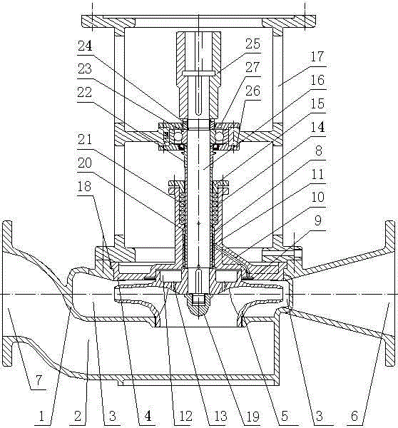
[0034] Such as figure 1 As shown, a long-life energy-saving single-stage centrifugal pump includes a pump body (1), a pump suction chamber (2), a pump press-out chamber (3), and a pump cover (4), which are located at the lower part of the pump body (1) It is the suction chamber (2) of the pump, the upper part is the press-out chamber (3) of the pump, the pump cover (4), the impeller (5), the pump cover (4) covers the upper part of the pump press-out chamber (3), and the impeller ( 5) Rotate at a high speed in the pumping chamber (3) to make the liquid in the impeller (5) form centrifugal force, which is converted into pressure in the pumping chamber (3). The liquid is continuously pressed out from the outlet (6) of the press-out chamber, so the suction port of the impeller (5) forms negative pressure and continuously sucks the liquid from the suction chamber (2) of the pump, and continuously from the inlet (7) of the pump suction chamber Replenish the liquid to complete the delivery of water or liquid. There is a water mold bearing (8) at the bottom of the pump cover (4). The pressure water of the water mold bearing (8) comes from the pump's press-out chamber (3), filtered by the ring filter (9), and then passed through the delivery pipe (10) , Enter the water mold bearing (8), pass 4 to 12 orifices (11), and distribute to the static pressure cavity of the water mold bearing (8) to form a rigid hydrostatic water film on the pump shaft (16). The lubrication method changes the sliding friction of the conventional sliding bearing into a rigid hydrostatic water film slip, and separates the high-speed rotating pump shaft and the water film bearing with a 0.03 to 0.05mm hydrostatic water film to make the pump shaft and the water film separate The bearing does not produce friction and becomes a water film bearing that does not wear. Since the pressure water of the water model bearing comes from the pump's press-out chamber, the supply of pressurized water during the pump operation will not be interrupted and the formation of a static water film will not be maintained. Discontinuous, so the continuity and effectiveness of the water model bearing in the working process are guaranteed.
[0035] Energy-saving measures 1: The water model bearing is a frictionless bearing-reducing energy consumption without friction-it is an energy-saving bearing.
[0036] On the pump cover (4), an annular filter screen (9) is arranged in the inner cavity of the pump press-out chamber (3). This ring-shaped filter screen (9) obtains the pressure of the natural rotation in the pump press-out chamber (3) The water is scoured without being blocked, so the filtration accuracy can reach 10~15μm, and the diameter of human hair is about 60~80μm. Therefore, it is ensured that the fine sand cannot enter the water model bearing and the safe operation of the water model bearing. . And the connecting conveying pipe (10) is directly casted inside the pump cover (4), so that the structure design can be realized.
[0037] In the lower part of the water model bearing (8) is a negative pressure cavity (12), which ensures smooth drainage of the water model bearing due to the action of negative pressure, thereby ensuring the self-adjusting ability of the water model bearing.
[0038] The negative pressure chamber (12) is connected with the suction port of the impeller (5) through the balanced suction hole (13) to form negative pressure.
[0039] Energy-saving measures 2: Due to the high positioning accuracy of the water model bearing, and no cantilever,
[0040] The sealing gap between the impeller and the sealing ring is smaller than that of conventional pumps, and the reduction of the sealing gap is equivalent to reducing the internal leakage of the pump, so the volumetric efficiency of the pump is improved-effective energy saving 1~1.5%.
[0041] Energy-saving measure 3: The upper part of the water film bearing (8) is the stuffing box (14) and the packing gland (15). The packing gland (15) is used to adjust the packing force to achieve the seal between the pump shaft (16) and the outside world. Performance can be adjusted. Because the flow of pressure water is limited by the set value when the pressure water flows through the orifice, and the lower part of the water model bearing is negative pressure, the leakage pressure between the pump shaft and the outside is lower than that of the conventional pump, so the packing force can be less than the conventional The pump has less leakage, reducing the holding force is equal to reducing the friction of the packing on the pump shaft, and further energy saving.
[0042] Energy-saving measure 4: Deep groove ball bearings (23) are used on the pump shaft (16). Since the upper and lower sides of the impeller (5) are negative pressure chambers (12), the axial force generated by the impeller's water delivery is basically balanced, and the axial force borne by the ball bearing ≈ the weight of the pump shaft and the impeller. In the same way, the pump shaft basically has no cantilever, and the radial force on the pump shaft is basically concentrated in the hydrostatic bearing part, so the axial force and radial force assumed by the deep groove ball bearing are slight. Therefore, it is ensured that the bearing is durable and has low friction and saves energy.
[0043] There is a motor seat (17) on the upper part of the pump body (1), a pump cover (4) is fixed between the pump body (1) and the motor seat (17), and the end faces of the pump body (1) and the pump cover (4) are sealed Glue (18) to ensure the sealing of the press-out chamber.
[0044] The upper part of the motor seat (17) is equipped with a motor, the middle part is provided with the upper bearing of the pump shaft, and the lower part is the pump cover and the pump body. The three supporting points are formed inside an object, that is, the inside of the motor seat is formed, ensuring three supports The coaxiality of the points ensures the stability of pump operation and low noise, low vibration, and low heat generation.
[0045] There is an impeller nut (19) at the lower end of the pump shaft (16) for fastening the impeller (5). The impeller is connected in sequence: water mold shaft sleeve (20), packing shaft sleeve (21), bearing stop sleeve (22), deep groove ball bearing (23), bearing nut (24), coupling sleeve (25). All shafts are protected by various sleeves so they are durable.
[0046] The lower bearing cover (26) and the upper bearing cover (27) are equipped with sealing devices to ensure that the bearing runs without dust and is durable.
[0047] The above is an embodiment of a vertical long-life pump, which is an independent liquid conveying device, and its structure and principle can also be applied to a horizontal long-life pump, and it can work with any power equipment.
[0048] The longevity pump has a flow range of 3-720M3/h, a head range of 8-120M, and a power range of 0.37-200Kw.
[0049] Based on the above-mentioned exquisite design, all aspects have been achieved to the extreme. It is estimated that the maintenance-free operation time of the long-life energy-saving single-stage centrifugal pump can exceed three to five years.
[0050] Combining the above-mentioned exquisite design, all aspects of energy-saving solutions have achieved the ultimate. It is estimated that the long-life pump can increase the efficiency by 2-3% compared with the conventional pump.
[0051] The utilization rate of single-stage centrifugal pumps in centrifugal pumps exceeds 80%, while the average efficiency of conventional pumps after friction and wear will drop by 5-12%. As long as they can still run, general users will not replace pumps. This is a common phenomenon. This intangible waste causes a waste of more than 31 billion Kw/h of electricity for our country every year. In 2012, my country's total electricity consumption was 4,959.1 billion Kw/h, of which various pumps accounted for 25% of my country's total electricity consumption. The estimated pump electricity consumption was 1239.8 billion Kw/h. If the pump efficiency is increased by 2.5~6.5%, my country can save 31~80.6 billion Kw/h of electricity every year. Estimation based on 1 ton of coal power generation = 3333 kilowatt-hours of electricity: my country can save 930 to 248 million tons of coal for power generation each year, which is a huge contribution to the protection of our environment and investment.

PUM

no PUM

Description & Claims & Application Information

We can also present the details of the Description, Claims and Application information to help users get a comprehensive understanding of the technical details of the patent, such as background art, summary of invention, brief description of drawings, description of embodiments, and other original content. On the other hand, users can also determine the specific scope of protection of the technology through the list of claims; as well as understand the changes in the life cycle of the technology with the presentation of the patent timeline. Login to view more.

Similar technology patents

Glomerocryst cubic boron nitride composite sheet and preparation method for same

ActiveCN103158287AExtended service lifeIncreased depth of cut
Owner:ZHENGZHOU BERLT HARD MATERIALS

Sleep assistance mattress

ActiveCN106842979AReduce data processing pressureExtended service life
Owner:DONGGUAN UNIV OF TECH

Application of epoxy cardanol as bio-based hindered phenolic antioxidant

InactiveCN105219458AGood antioxidant propertiesExtended service life
Owner:INST OF CHEM IND OF FOREST PROD CHINESE ACAD OF FORESTRY

Classification and recommendation of technical efficacy words

  • reduce axial force
  • Extended service life

Vertical Woltmann water meter

InactiveCN102322901Areduce axial forcehigh sensitivity
Owner:TIANJIN JINMIAO WATER METER MFG

Radial flow type turbo expander structure

ActiveCN112096460Areduce axial forceImprove operational reliability
Owner:NO 711 RES INST CHINA SHIPPING HEAVY IND GRP

Gear box oil pump having oil unloading structure, and gear box

PendingCN109113986Areduce axial forceExtended service life
Owner:江阴华欧德汽车动力系统研发有限公司

Fracturing manifold quick connecting device

Owner:YANTAI JEREH PETROLEUM EQUIP & TECH

Modified asphalt composition with creeping characteristic and preparation method thereof

InactiveCN102020859Aavoid rapid agingExtended service life
Owner:ZHEJIANG WOPUMAN HIGH NEW MATERIALS
Why Eureka
Try Eureka