
Energy-saving environmentally friendly material drying device

A drying device, energy-saving and environment-friendly technology, which is applied in the direction of heating device, drying solid materials, drying, etc., can solve the problems of affecting normal discharge, troublesome cleaning, dust deposition in the inner cavity of the dryer, etc., so as to improve heat utilization rate and improve Heat exchange area, effect of large heat exchange area

Inactive Publication Date: 2014-10-08
邓大贵
View PDF7 Cites 1 Cited by
  • Summary
  • Abstract
  • Description
  • Claims
  • Application Information

AI Technical Summary

Problems solved by technology

[0002] Existing materials (such as coal) must be pulverized with a ball mill before use. However, if the coal is not dried before entering the ball mill, it will affect the normal discharge; some choose to pass it before entering the ball mill. The heating device of electric heating can dry the surface of coal, but the drying of coal is not thorough enough. After a long time, it will also affect the normal discharge of the ball mill.
[0003] Then the material dryer appeared. Due to some defects in the structural design of the material dryer, it is easy to deposit dust in the inner cavity of the dryer after a long time, and it is very troublesome to clean.

Method used


Image

  • Energy-saving environmentally friendly material drying device
  • Energy-saving environmentally friendly material drying device
  • Energy-saving environmentally friendly material drying device

Examples


Embodiment Construction

[0029] Below in conjunction with accompanying drawing and embodiment the present invention will be further described:

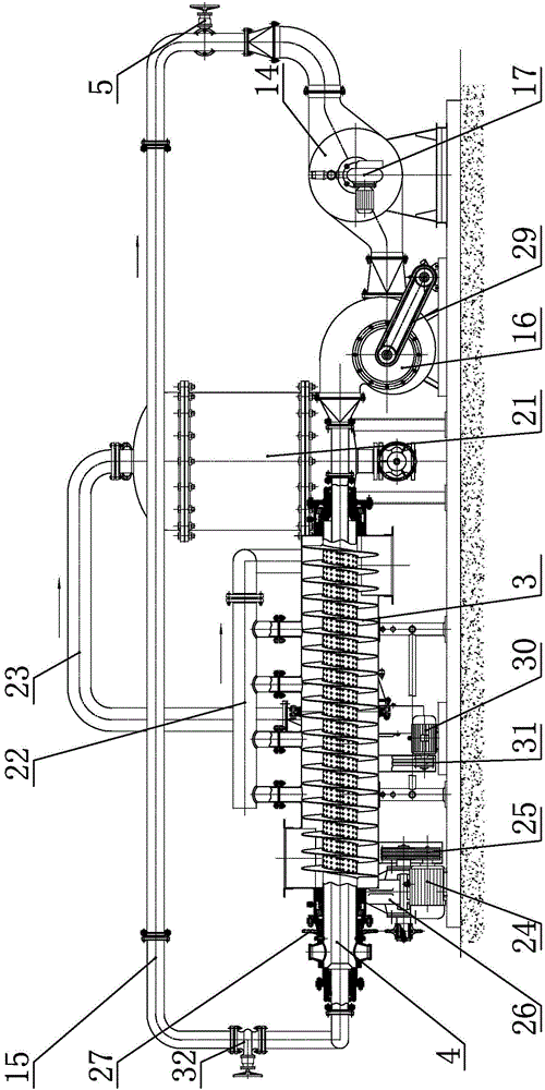
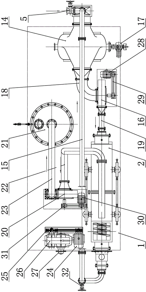
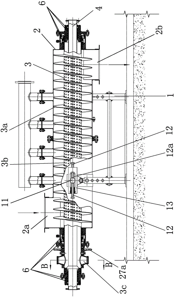
[0030] combine figure 1 —— image 3 As shown, an energy-saving and environment-friendly material drying device is mainly composed of a material dryer, a hot air transmission part and a dusty water vapor treatment part.

[0031] combine image 3 , Figure 4 As shown, the material dryer is mainly composed of a dryer shell 2, a drying pipe 3, an air distribution pipe 4, a first bearing 6 and a first power mechanism. The shell 2 of the drier is arranged horizontally and is preferably cylindrical. The dryer shell 2 is installed on the base frame 1, and the base frame 1 is used for supporting and fixing the dryer shell 2.

[0032] The dryer shell 2 is provided with a feed port 2a and a discharge port 2b, and the material enters from the feed port 2a and is discharged from the discharge port 2b (such as image 3 indicated by the middle arrow). The drying pipe...


PUM


Abstract

The invention discloses an energy-saving environmentally friendly material drying device. The energy-saving environmentally friendly material drying device comprises a material drier, a hot air conveying part and a dust-carried water vapor processing part, wherein an outer shell of the drier is installed on a basic frame, a drying pipe is horizontally installed in the outer shell of the drier, a branch air pipe is installed in the drying pipe, and first bearings are installed between the two ends of the outer shell of the drier and the two ends of the drying pipe and between the two ends of the drying pipe and the two ends of the branch air pipe respectively so that the drying pipe can rotate relative to the outer shell of the drier and the branch air pipe. A spirally wound heat radiation fin is welded to the outer wall of the middle of the drying pipe, a hot air via hole is formed in the outer wall of the branch air pipe, and the basic frame comprises a fixing supporting frame and four adjustment shaft rods. The drying pipe with the spiral fin rotates to push materials to advance, so that the thorough heat exchange is carried out on the materials, the dust-carried water vapor is prevented from being directly discharged into the atmosphere and polluting the environment, the purposes of saving energy and protecting the environment are achieved on the premise of guaranteeing that the materials are thoroughly dried, the material drier can be obliquely installed, and automatic ash discharging is facilitated.

Description

technical field [0001] The invention relates to a device for drying materials, belonging to the technical fields of mechanical structure, energy saving and environmental protection. Background technique [0002] Existing materials (such as coal) must be pulverized with a ball mill before use. However, if the coal is not dried before entering the ball mill, it will affect the normal discharge; some choose to pass it before entering the ball mill. The heating device of electric heating can dry the surface of coal, but the drying of coal is not thorough enough, and the normal discharge of ball mill will also be affected after a long time. [0003] Then there was a material dryer. Due to some defects in the structural design of the material dryer, it is easy to deposit dust in the inner cavity of the dryer over time, and it is very troublesome to clean. Contents of the invention [0004] The present invention improves on the above technical problems and intends to provide a m...

Claims


Application Information

Patent Timeline
Patent Type & Authority Applications(China)
IPC IPC(8): F26B17/20F26B23/10F26B25/00
Inventor 邓大贵向鹏庹钦财秦玉琴
Owner 邓大贵
Learn More