
Unfolding and locking device for foldable rudder face

A technology of locking devices and folding rudders, which is applied in the direction of projectiles, offensive equipment, weapon types, etc., can solve the problem that it is difficult to ensure the synchronization of the movement of the rudder surface, it is difficult to meet the requirements of the outer envelope space of the carrier aircraft, and it is impossible to apply the airborne Guided weapons and other issues, to achieve the effect of simple structure, reliable mechanism, and elimination of gaps

Active Publication Date: 2014-10-08
CHINA AEROSPACE TIMES ELECTRONICS CORP
View PDF6 Cites 28 Cited by
  • Summary
  • Abstract
  • Description
  • Claims
  • Application Information

AI Technical Summary

Problems solved by technology

[0003] The traditional folding method of the rudder surface used for small missiles and box-type launch guided weapons adopts a torsion spring structure. After folding, it needs to be restrained by the launch tube wall, and it will automatically unfold after being released from the constraints. This kind of unfolding form requires a tube wall and cannot be applied. on airborne guided weapons without launch tubes
The folding method of guided weapons used in service mostly adopts horizontal folding. When the diameter of the guided weapon itself is small and the control rudder surface has a large extension, it is difficult to meet the load capacity of small-diameter missiles after the rudder surface is folded horizontally. Envelope Space Requirements Outside the Machine
Since guided weapons generally have multiple control surfaces at the same time, the traditionally used rudder surface folding often sets up an independent folding and unfolding mechanism for each control surface. This mode requires a relatively complicated rudder surface deployment signal control system, and at the same time It is also difficult to guarantee the synchronization of

Method used


Image

  • Unfolding and locking device for foldable rudder face
  • Unfolding and locking device for foldable rudder face
  • Unfolding and locking device for foldable rudder face

Examples


Embodiment Construction

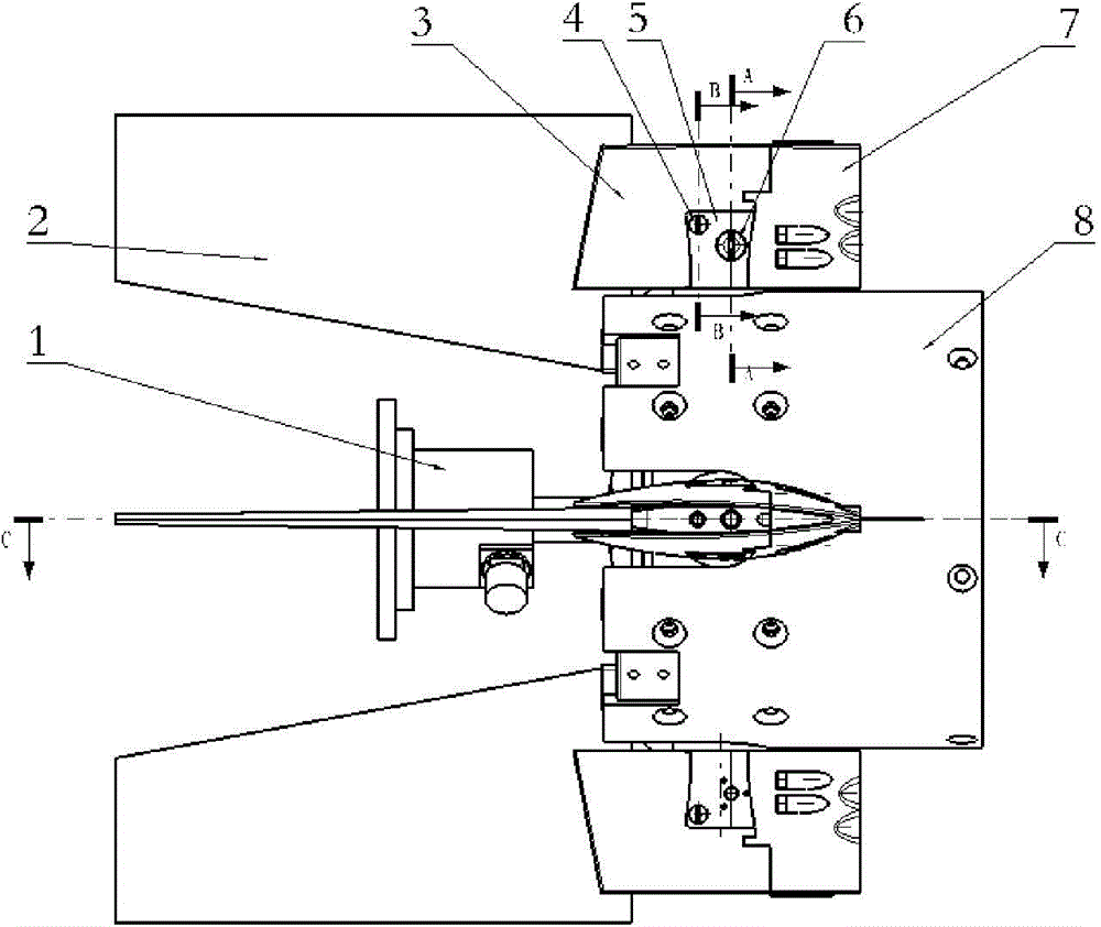
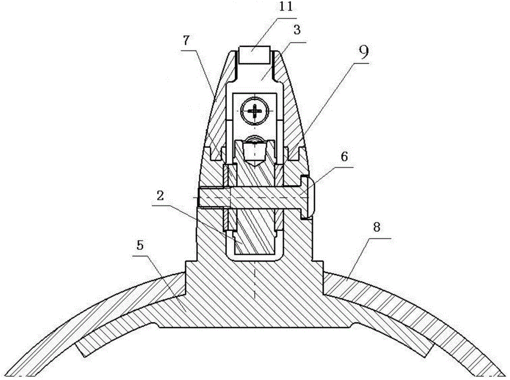
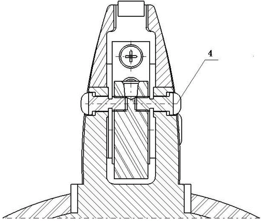
[0022] As shown in the figure, an unfolding and locking device for a folded rudder surface includes an ignition cylinder 1, a push plate 10, a rudder shaft 5, a tiller rear seat 7, a tiller 3, an upper locking pin 12, and a lower locking pin 13 , upper locking spring 14, lower locking spring 15, thrust bearing 9, cabin body 8, wherein rudder shaft 5 one end is installed on the cabin body 8, and the other end is fixedly connected with tiller handle 3, and rudder surface 2 is installed on the rudder shaft 5 by The thrust bearing 9 is supported and fixed by the shaft screw 6, and the shaft screw 6 passes through the through hole on the right side of the rudder shaft 5, the thrust bearing 9, the rudder surface 2, and the thrust bearing 9, and then is screwed to the left side of the rudder shaft 5. In the hole, a well-designed tolerance can ensure its flexible rotation; the thrust bearing 9 is arranged between the rudder surface and the rudder shaft, the tiller rear seat 7 is instal...


PUM


Abstract

The invention discloses an unfolding and locking device for the foldable rudder face. The unfolding and locking device comprises a fire work moving cylinder, a push plate, the rudder face, a rudder spindle, a rudder tiller rear base, a rudder tiller, a thrust bearing and a cabin. The rudder face is supported by the thrust bearing. The rudder face is fixedly connected with the rudder spindle connected to the cabin. The rudder tiller and the rudder tiller rear base are clamped with each other. The rudder tiller rear base is installed on the rudder tiller. One end of the rudder tiller rear base is provided with a damping pad. An upper locking pin, a lower locking pin, an upper locking spring and a lower locking spring are installed in the rudder tiller rear base, wherein the upper locking pin and the lower locking pin are used for locking the rudder plate. The fire work moving cylinder is fixedly connected with the push plate. By the adoption of the mode of combining the fire work moving cylinder and the push plate, the rudder face is pushed to be unfolded, and therefore the unfolding and folding device is simple in structure, low in cost and easy to realize.

Description

technical field [0001] The invention relates to a device for controlling the unfolding and locking of a folded rudder surface, which can be applied to various airborne air-to-ground guided weapons that need to fold the rudder surface. Background technique [0002] With the continuous innovation and development of aviation technology and guided weapons, airborne guided weapons are required to minimize the space occupied by the aircraft when on-hook, especially under the requirements of improving the stealth performance of military aircraft, airborne guided weapons are generally required style of mounting. On the other hand, guided weapons often require larger aerodynamic control surfaces to obtain sufficient aerodynamic control torque in order to obtain higher control maneuverability. The folding technology of the rudder surface has become the key technology to solve the contradiction between the control surface of the guided weapon and the mounting space of the carrier airc...

Claims


Application Information

Patent Timeline
IPC IPC(8): F42B10/14
Inventor 韩凌攀张俊何泓霏冯谦侯小平刘海静杨士超许昌吴冰高秀花宋永刚刘永超宋金来万军
Owner CHINA AEROSPACE TIMES ELECTRONICS CORP
Learn More